Living off the grid is an appealing goal for many in the hacker community, perhaps because it can fulfill the need to create, to establish independence, to prepare for the apocalypse, or some combination of all those things. [Buddhanz1] has been living off the grid for awhile now by harnessing power from a nearby stream with an old washing-machine-turned-generator.
He started with a Fisher & Paykel smart drive, which he stripped down to the middle housing, retaining the plastic tub, the stator, the rotor, the shaft, and the bearings. After a quick spot check to ensure the relative quality of the stator and the rotor, [Buddhanz1] removed the stator and rewired it. Unchanged, the stator would output 0-400V unloaded at 3-4 amps max, which isn’t a particularly useful range for charging batteries. By rewiring the stator (demonstration video here) he lowered the voltage while increasing the current.
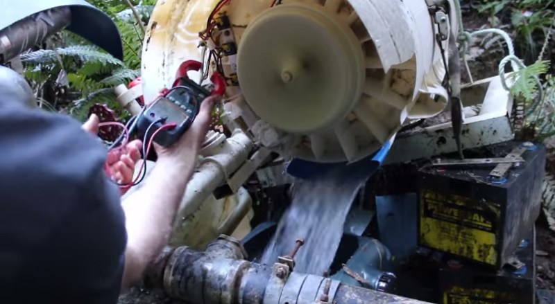
The key to this build is the inclusion of a pelton wheel—which we’ve seen before in a similar build. [Buddhanz1] channeled the water flow directly into the pelton wheel to spin the shaft inside the tub. After adding some silicon sealant and an access/repair hatch, [Buddhanz1] painted the outside to protect the assembly from the sun, and fitted a DC rectifier that converts the electricity for the batteries. With the water pressure at about 45psi, the generator is capable of ~29V/21A: just over 600W. With a larger water jet, the rig can reach 900W. Stick around for the video after the break.
[Thanks Paul]


Haven’t this been featured here before? Anyway, how would one regulate the voltage and frequency for such a setup? How important is it that these variables stay stable in practice?
He uses 3 phase generator converted to DC to charge the battery. Then you use the DC from the battery with an inverter, so that takes care of the whole AC thing…
The article mentions that the generator’s output is DC rectified at the end, so as long as a suitably sized filtering capacitor is added, the frequency should be insignificant as the output will be filtered DC. As for the voltage, it is probably going through some form of switching voltage regulator before charging a battery bank ( I’m guessing a 24V circuit ), further filtering noise and outputting a steady voltage.
Dosen’t matter for charging battery they don’t care how noise the power rail is. You just don’ want the battery above or below it voltage max or min.
“The key to this build is the inclusion of a pelton wheel”
I thought the key was having a great source of water at 45psi?
45psi on your own property definitely helps alot while harvesting power.
Requires a ~102in/8.5ft/2.6m drop. I’d imagine properties with cleanish flowing water would have a sufficient difference along the water’s path.
Maybe you swapped feet for inches… 45 psi needs 104 feet of head. In another video he states he has 48 meters of head on a 200 meter run of pipe.
So there would probably be quite a bit of searching to find a place that can support a system like this…
Yeah, 45PSI doesn’t sound right. 48M of head doesn’t sound plausible for his stream.
This would help: http://en.wikipedia.org/wiki/Gravitation_water_vortex_power_plant
He could have gotten straight AC, without any hard work, and then do what he wants (connect battery charger etc):
http://www.arthropodsystems.com/AsynchronousGenerator1/AsynchronousGenerator1.html
Or if he is not connected to the grid, same thing with few capacitors: http://www.arthropodsystems.com/AsynchronousGenerator1/AsynchronousGenerator2.html
The only problem is the generator needs to spin at exactly the right speed or the frequency will be off.
If you look at the data given on linked page, you will notice that frequency remains almost the same for more than 3x change in driving power (for grid connected system). Therefore, speed control can be rather crude and still work. You only need to cut the generator off the grid if shaft spins at less than 1800 rpm (1500 rpm Europe) to prevent motoring. For stand-alone system not connected to grid this is admittedly more difficult.
it’s good for rural areas where your electrical usage is kept at a minimum. he might consider a shut off valve to save bearing wear once all his power storage and heat requirements are topped off.
Having seen a number of projects now built from rewired common motors (or car alternators), I always wonder – how efficient are these consumer goods at converting force to electricity, compared to a high-quality and purpose-built generator? I don’t need exact numbers, just curious whether the efficiency is fairly close, or if there’s a difference large enough that for DIY electrical production something better and more expensive might be worth considering.
The F&P motor is super efficient at this speed range and much much better than a regular car alt or whathaveyou . Its why second hand units are in so much demand in this sector.
Electricity converts to magnetism and then to kinetic energy and heat. Reversed – kinetic energy converts to magnetism and then to electricity and heat.
In both cases the heat is dissipated by friction/bearings and the electric coils of wire (and a little from the rectifiers).
In theory – as the electrical properties of the coils are constant, the efficiency in the reversed energy direction should be the same within the power range the motor normally run at.
Motors are normally designed for good efficiency because if they weren’t they would quickly overheat.
If you lack an old washing machine you can use old car or truck alternators: they’re already wired to output the right voltage plus loads of current to charge batteries and can be found cheap.
On a side note, stepper motors also make some decent generators for experimenting. I’m not sure of their mechanical robustness as they’re not intended to turn continuously but anyway they do output some good energy. As an experiment, take two identical steppers and wire them in parallel, that is each wire with the same wire on the other motor, then turn one of them and watch the second following step by step.
Except you have to gear them up them alternators to generate anything useful. An old Amtek tape drive motor or a DIY neo generator are better alternatives if you don’t have an F&P.
http://www.otherpower.com has a couple of good articles on a guy who has a water-powered generator setup that has been modified over the years….
I don’t understand why he rewired the unit rather than use a switching power supply to convert to a convenient output. Though perhaps this wasn’t a “wind new coils” rewire.
Probably because it’s more efficient to avoid another conversion step?
The output is three phase and the frequency would very a lot and may not even be close to correct. Even if the frequency was right all the time you still have the extra complexity of a three phase output.
What flow rate at 45 psi for 600W? GPM?
Pretending that it’s 100% efficiency:
$ units
You have: 600 watts / (45 psi)
You want: gallons/minute
* 30.651933
i assume that the rewire (though i didnt follow the link) means putting some of the coils that are in series, in parallell instead.
that is probably needed in order to not excceed maximum voltage on the semiconductors following (bridge rectifier, charge controller…), though one ought to pay attention to the maxim current specs instead. those are far harder to exceed, and can be easily managed by installing parallel rectifiers.
this is an easy build for any novice with some electrical skills, and circumvents the more tricky part of voltage and frequency regulation by adjusting the water inflow.
it could certainly be made better if it would include that, but that also adds more points of failure, and the increase in harnessed power would be marginal.
what bothers me is the fact that his bearings overheated before. that calls at least for some sort of electric shutoff of the water inlet with a valve. it could probably be done very easy with a cleverly placed thermocouple and the existing PLC (nice touch about that one being cheaper than a charge controller… goes to show that prices are driven by the market, since a plc is a far more versatile tool than a chare controller, though you could probably build yourself one of those 555 chip controllers…). that is, if the plc can read a thermocouple, which i assume it should be able to, considering that it needs some analog inputs to monitor battery voltage. even if it does not have a dedicated thermocouple input, you should be able to at least read the voltage caused by too high a temperature. accuracy is not required…
the reason why parts of this bother me, is that after 25 years of life, i have come to not only appreciate tinkering, but also greatly despise the need of having to constantly monitor and adjust something that is not supposed to be a prototype, but an actual device that you use…. i certainly wouldnt want to periodcally worry about something as important as my generator.
if i’d have a go at this type of project (and i hope i will, at some point, after i get a proprety with suitable water resources) i’d go a bit less redneck and use a microcontroller on this project, so that i can add whatever features i deem necessary, including those mentioned before.
but i realise that is something for people not afraid to acquire the necessary skills, and it’d probably involve using an oscilloscope.
i’d go as high in frequency as possible, and add a voltage regulating multitap transformer. the higher the freq., the smaller the transformer would need to be.
i’d also probably try to use more fluctuating resources, such as wind and solar, and that would probably benefit greatly from some maximum power point tracking.
but all those are complications and pains in the ass that this project does not have, hence it gets my thumbs up.
^ cocaine? how much did you do before posting?
let’s just say i have thought about the topic a lot recently…
do you feel any of my commets are out of place?
no point in engaging the trolls dude….
He probably had the bearing meltdown as he started with a second hand unit. Even with thermal protection the bearings will still need to be replaced periodically. If you start with new bearings then you would have some idea of how long they last and just replace them more frequently than that.
I probably wouldn’t go down the path of increasing the frequency to reduce the costs of a step transformer when it would be just as easy to rewind a Microwave Output Transformer as it is in the power range he mentioned and there easy to find cheep or free.
I am assuming the output is close to 50/60 Hertz. In normal use the motor is driven from switched DC so I have no clue to what the frequency might be.
The original coil is three phases of 14 series coils and what looks like 14 magnets. The rewound coil is three phases of 7 groups of two series coils.
The output frequency would be Hz = RPM * 14 / 60 so RPM = Hz * 16 / 14.
So 50Hz would be about 215 RPM
A google shows that there are different versions of this motor with different numbers of magnets.
Correction – RPM = Hz * 60 / 14
How well does this prevent rust and corrosion from being an issue? Most washing machines protect the motor from water but this isn’t a typical application and the motor is being inverted and used as a generator.
Inverting the motor “mission” does not changes anything. It’s still housed out of water, and will not get too much more moisture than before the conversion.
The motor is still sitting directly above water. Water evaporates.
first off, I want to say I absolutely love this but there are a few points I believe this guy could improve on:
1) those bearing overheated, there should be some sort of temperature regulation or a cheap fan or five?
2) given the scrap parts involved, maybe a second or third machine with a water reservoir could be a wiser choice for peak demand for his house and would last longer with contingency for failure.
3) aren’t there cheaper pelton wheels than £60-70, that could be printed in 3 dimensions perhaps? (although this is coming from a guy in london who works around a corner from a walk in 3D printer shop). mabey just some halved and bent PVC pipe stuck on a wooden ring, less efficient but this is about bang for buck not for finessing every gram like nasa.
4) I think the electronics weatherproofing leaves a lot to be desired.
Just dont try this in places like Florida where there are laws that prohibit you from not having a connection to the city electricity grid…
…and many other places have strict water use laws with huge fines…
Here you can have it disconnected if you want, but you must still pay for the connection…
The author mentions he has about 45 psi pressure driving – this means his water source is 110 feet above him or he’s running it with a faucet and the whole thing is a scam.
I was curious on the same thing so I dug through his old videos: https://www.youtube.com/watch?v=KaXmeegaRUE
Now I understand
If only there were some source of cool water to keep those bearings from burning up!
Why does he enclose and make watertight the compartment that has a water jet and a Pelton wheel in it?
Love the video, it’s a great document. Time to poke around thru his links…
1) great build, im sure he will sort out the bugs
2) some commentor mentioned paralleling diodes.
yeeeh, maybe, never, usually, probably not, you shouldnt, it depends…
3) nobody mentioned WHY his bearings failed ?!?!?!?!
so you just (silently) laugh at the poor guy?
not telling him why is mean and cruel.
he is going out of his way and using his time to show you what he did.
he’s going to loose ANOTHER bearing set / scrap washing machine
bearings designed to operate vertically fail early when used horizontally
and
bearings designed to operate horizontally fail early when used vertically
if a bearing vendor does NOT ask you what orientation you need,
he’s either clueless or a lying shiester
I suspect a much simpler cause. All bearings have a service life and the donor washer was already used. Plus all designs have a intended service, in this case the designer intended the washer to be used maybe 4 hours a week? Now start running the used bearing 24X7 and I would expect a failure within a year!
I have to chime in here… with this new found knowledge, couldn’t he just change the orientation of the generator to sit in the same vertical position the washing machine was designed for? Problem solved. Cooling find fashioned out of aluminum and extended into the waste water could dissipate heart, similar to a heat sync on a laptop cpu…
He would just need to extend his pvc piping to rotate his nozzle jet to line up with the p-wheel…
The bearing failure has very little to do with cooling – the overheating is a byproduct of increased friction as the bearings wear and probably additional breakdown of the lubricant (they’re most likely sealed). Lets not forget that, while the motor may be of ‘higher-than-average’ quality, it’s still a commercial product which as been designed for a given lifetime based on limited usage, so the bearings in question may not be of the highest quality. I’m willing to bet that replacing them during the initial build will increase the lifetime of the generator dramatically.
that was me, and i also thought abou, but never mentioned, some high wattage low ohm power resistor network or something.
i never intended to make a feasable design in a HaD comment. i meant that there are always handy solution for “i need to pass more current through this”, than “the voltage is too high”.
This has me wondering about using this with wind.
Is there some way to feed 240v into a power outlet in phase so as to offset the power usage from the grid?
Yes. See 2nd and maybe 3rd link in comments above for example.
they are called synchronised dc to ac converters. they generate the specified freq (50 or 60 hz) to be in phase with the grid, at a slightly higher voltage, to pump current into it, instead of out of it.
also called grid tied inverters.
If you need more information on this check out ecoinnovation.co.nz. Mike Lawley has developed a very sophisticated business packaging these smart drive motors into both hydro and wind generators. The motors are a New Zealand innovation and the video I suspect is also made here, finding water isn’t usually a problem in NZ.