I2C has a seven-bit address space, and you’re thinking “when do I ever need more than 127 devices on a pair of wires?” So you order up some parts only to find that they have one, two, or three user-configurable address pins for any given device type. And you need a bunch more than four or eight capacitive sensor buttons on your project. What do you do?
If you’re reader [Marv G], you think outside the box and realize that you can change the addresses on the fly by toggling address pins high and low with your microcontroller. That is, you can use a single I2C address pin for each device as a chip select signal just like you would have with SPI.
That’s it, really. [Marv G] goes through all of the other possible options in his writeup, and they’re all unsavory: multiple I2C busses, a multiplexer, buying different sensors, or changing micros. None of these are as straightforward as just running some more wires and toggling these with your micro.
We’d even go so far as to suggest that you could fan these chip select lines out with a shift register or one of those 1-of-N decoder chips, depending on how many I2C devices you need to chip-selectify. (We’re thinking 74HC595 or 74HC154.)
Along the way, we found this nice list of the number of address pins for a bunch of common peripherals provided by [LadyAda], in case you don’t believe us about how ubiquitous this problem is. How many devices on that list have one (1!!) address pin?
At the end of his post, [Marv G] asks if anyone else has thought of this chip select trick before. We hadn’t. Here’s your chance to play the smart-ass in the comments.


This is covered in detail in many I2C devices’ datasheets.
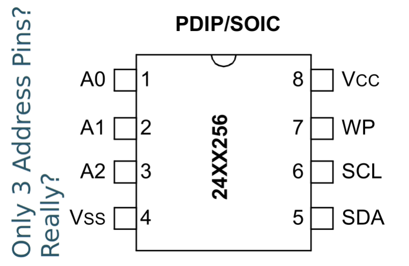
For instance, from the Microchip 24LC256 EEPROM datasheet…
“In most applications, the chip address inputs A0, A1
and A2 are hard-wired to logic ‘0’ or logic ‘1’. For
applications in which these pins are controlled by a
microcontroller or other programmable device, the chip
address pins must be driven to logic ‘0’ or logic ‘1’
before normal device operation can proceed.”
Nice find. I worked with many I2C devices in the past, however this was new to me. Also, this problem is probably not common when addressing memory chips, since you can always find a different one that is large enough for your application.
Yeah, this is definitely not a new find.
Possible pitfall: make sure to scan the datasheet of your chip to make sure it samples the input pin on each transaction; I’ve worked with ICs before that sample the address pin(s) on power-up, and never look at them again.
We have found this too. Specifically with this digital pot from MIcrochip: MCP4531T-103E/MF read the address lines on power up only then they can’t be used for chip select.
Clever trick! No, I hadn’t thought of it. It does mean each device type has to have a reserved unusable address, but that seems like a reasonable price to pay.
If you have extra I/O lines on you uP, might as well use them as extra I2C ports. Multiple I2C devices can easily share the clock line, and just use that “chip select” line as the data line in bitbang code and you are set.
I2C hardware on the uP are so primitive, if you have to get an interrupt per byte transferred, handle the last byte differently and error conditions, they might as well be in a bit bang software loop. There are some uP with DMA options, but once again if you are going to transfer a small # of bytes per device, the overhead is way too much.
Having multiple (or isolated ones via muxes) I2C actually quite useful in fault tolerant systems as faulty I2C device (e.g. on a card in a chassis) can hang the whole bus by pulling the data line low. I2C muxes or multiple I2C also gets around the capacitive load issues with large number of devices and long cables/PCB traces. So they are things to be considered if you run into signal quality issues.
nah thats slower. You still need to ‘do stuff’ to drive that sw port.
With addresses its actually one single bit flip and jualla you are ready to go . A single instruction no matter how you code it , risc or c or what ever. In assembly its one line.
The old I2C speed is only 400k bits/s which is well within what one can easily bit bang. Even the original intel 8051 at 12MHz (internal at 2M cycles/s and multiple cycles per instructions) can almost bitbang close to 100k bits/s. So the slow part on any recent uP isn’t going to be an issue.
As for code, I have done a lot of I2C implementation in C bit banging, verilog, Freescale K22 i2c hardware and all of them directly from specs and datasheets.
It is a non-issue for the average person that is going to copy/paste a library anyways.
for hobby stuff , not a big deal being slow. For actual product designs (kind of thing this would be used in) you never know how much they are utilizing or not. Take an apm for instance being pushed right to the limits of its ability. You can still end up with out a nice clean way to bang it out.
IMHO, what I have said is about hobby implementations. Chances are if you need more devices than the hard coded i2c addresses, you are doing it wrong. There would likely be more efficient implementations and parts. I would have used i2c muxes for segmenting the i2c bus and not having to kludge things. For i2c mux, you can use hardware i2c you want.
To be honest, I would not use i2c peripherals in the first place if there are alternatives e.g. SPI. They are a pain for the software drivers, error handling.
ugh, yes. spi is so easy and intuitive. makes my life a breeze.
I2C / SMBus is much more standardized than SPI, which makes it extremely straightforward for most peripherals. SPI is a disaster for beginners and pros to get going — clock phase, clock polarity, chip-select state, MSB vs LSB, register access vs proprietary protocol…. it’s all device-dependent. Almost *all* I2C devices these days implement SMBus, so you can call nice, high-level register_read() and register_write() commands that work on all ICs on the bus. Compared to SPI, I2C is also much more straightforward to work with on Linux, which is continuing to take over the embedded market for everything but the simplest devices. I would definitely always pick an I2C device over SPI for that reason alone.
Be careful when sharing the clock line — like the data line, it’s bidirectional, when you’re using slave devices that utilize clock stretching. I think you’re right that it should work, though.
Generally, proper clock stretching support, collision detection, etc are a good reason to use i2c hardware instead of bitbanging.
“I2C hardware on the uP are so primitive, if you have to get an interrupt per byte transferred, handle the last byte differently and error conditions, they might as well be in a bit bang software loop.”
Well, you have to do all of those things in a bitbang software loop, too. If interrupts bother you, don’t use interrupts for the hardware peripheral. Just poll on the flags.
I will say that a lot of I2C implementations, both software/hardware, are really pretty bad. TI’s eUSCI peripheral (especially combined with a DMA controller) is the first one I would consider ‘good.’
Already been said, Microchip designed the part like this .
Some more complex parts, such as ones that utilize an embedded microcontroller, might sample their address pins only once at startup.
Might be true, but with the ones I tested it worked just fine,
Your right. I remember a few devices I have encountered does this. It really depends on how “smart” the end device is.
The “smartest” I2C devices, those that are themselves based on an MCU, are likely the ones you’ll have problems with. In which case the programmer of that MCU may have never anticipated the address lines will change, and implemented nothing but an initial check on power-up. Even if they though of this, and tied the address lines to external interrupts which quickly reconfigure the hardware I2C, it still may not be fast enough to catch an I2C transaction which begins immediately after a change of address; depending on how fast that interrupt is serviced, whether the MCU core was in sleep, whether an address change can take effect only when hardware I2C is idle, etc. Such MCU-based devices are also more likely to use clock-stretching, causing issues with bit-banged I2C implementations on the host which don’t properly detect that.
The “dumb” purpose-built I2C devices are just a collection of gates, and ironically are less trouble. Saving the power-up state of the address lines isn’t done because it would require more gates, and be less straightforward than just comparing the received address to the immediate state of the address lines. They also typically respond fast enough to never need clock stretching.
Lots of I2C devices’ address lines aren’t digital. They’re very frequently analog, or semi-analog in bizarre ways. So not all of them *can* sample the address lines all the time.
Take the TMP102 and similar temperature sensors from TI – they have 4 addresses based on the state of 1 address pin. You might think “varying pullup resistors” or something like that, but no – you can connect ADDR to VCC, ground, SDA, or SCL. In those cases you can see obviously that it only samples it in certain cases.
Well the MPR121 (which is MCU based I guess) also allows it to connect either to VCC, GND, SDA or SCL. As stated in my article, apparently the pin is still read every time there is data transfer. It makes sense to some point: The device has to check whether the pin is connected to either of these 4 options, all of them are either high or low. Thus, to distinguish which one it is, there must be traffic on the bus – the device cannot just pull the SDA or SCL lines low on powerup, this would lead to undefined behavior on the other devices connected to the bus.
So let me get this straight, to add more devices they are sacrificing the 2 wire part of I2C, bearing in mind most I2C devices read the address pins at power up and keep that address until they power off? So this works with what, 3 out of every 10 devices?
I look forward to seeing the published results of your comprehensive survey of I2C device pinstrapping behaviour.
Regardless, his point that adding additional pins to control the address lines defeats the purpose of 2 wire still stands. Better off using SPI.
You are only “better off using SPI” if the device is available in an SPI variant and you have the money to go buying new parts. As an example I bought a $60 pressure sensor, which is more than half the total value of the device I am building. I am going to make that sensor work even if it requires giving up the “benefit” of I2C being a “two” wire protocol.
If I was doing this in a factory intending to churn out a few thousand devices, I would probably consider SPI, multiple I2C busses, alternative parts with different I2C addresses, or more exotic solutions.
You can also hardcode the addresses of the chips. Then each chip gets its individual I2C address. This is what microchip suggests in the datasheet. Therefore you don’t need digital pins of the controller. And you can also have a linear address range for your memory. Look at my blog: http://heliosoph.mit-links.info/512kb-eeprom-atmega328p/
heliosoph
Sure, I guess that’s the way everyone does it. However this idea comes in handy when these address aren’t enough. In my case it actually was an MPR121 which has only one address select pin, but I need 5 of those on same I2C bus.
Yeah, I think you’ve missed the point somewhat…
yup
You could even use an I²C I/O-Cip (e.g. PFC8574) to keep the “2-Wire” nature of I²C at least somewhat intact (for example when interconnecting boards inside your device)….
I am using this method for a project I am working on for a guitar player friend of mine. I have made a 5 channel programmable Looper for him that uses MCP23017 chips over I2C bus to expand the Looper to 10, 15 or 20 channels. I use this method to set the address of the master on the fly by allowing them to select Master, Slave1 or Slave2 via a LCD and Pushbutton. I then Programmatically set the chip’s address based on the user input using I/O pins. This way each Looper’s hardware is exactly the same, and can be used individually as a Master or connected to make Master Slave combinations. I have had zero issues with doing it this way.
Not a bad idea…never thought to do that. Some other ideas:
PCA9544 – 4 channel i2c multiplexer. It has it’s own slave address so you can write to it and select the downstream channel;
sn74CBTD3306 – intended as an i2c level shifter, but has enable pins so you can have multiple busses.
There’s a good App Note from Philips about i2c hubs, repeaters, and expanders. http://www.nxp.com/documents/application_note/AN255.pdf
Or…You could do like the product from China I came across recently. 4 of the same device, with the same address, on the same bus. You can’t read from the device, or even be sure all 4 devices received the data correctly…but if you’re the trusting type this may work for you.
Actually i mentioned this option in my article as well. I didn’t like the fact that you need another IC to do that – which usually also slows down the bus a bit.
The PCA9544, you mean? While it does slow down throughput on the bus because you have to do extra commands to switch back and forth between the busses, it does have the benefit of adding significant drive capability to its downstream I2C devices.
However, if you’re willing to sacrifice an IC pin for an enable (like you’re doing), and don’t mind adding an IC, an I2C bus buffer (like a PCA9515A, or the many equivalents) is the way to go. That will work for *any* device, not just devices with I2C address pins. Doesn’t slow the bus down at all, and no worries about confusing the slave. There are multi-pin versions of those guys too – the PCA9516 allows for connecting 4 downstream I2C busses (via pins).
PCA95xx work great for this. I’ve worked with systems that use trees of these to support hundreds of devices from a single master. Linux understands these switches, and can be easily set up so that each bus segment appears as a separate I2C device.
You asked for smartass… I’ll give you smartass!!
How about intelligently doing a design and not specifying parts that won’t work like not having enough address lines. How about designing using busses and parts that are compatible with your requirements from the beginning? If you want chip select, use SPI.
BAM!
We do specify parts that work, but our junk boxes don’t deliver.
More importantly, is every i2c part available as an SPI?
Having used both in an industrial products, well I can testify that I2C is a real pain to debug.
As soon as one device locks the bus, you’re out of luck. All the chain is down.
Also on the uCs I know (PIC, dsPIC, STM32) the Master I2C peripheral is terrible and buggy as hell. You should see in the datasheets all the errata and (sometimes lack of) work-around you have to implement to get it working.
SPI on the other hand is much simpler on the low-level and Protocol points of view, which makes it far easier to implement in silicon and thus far more robust. It’s also much much faster, with clocks that can reach 50MHz in some cases.
PONTECH I2C address lines for chip selects on the Quick240: http://quick240.com/quicki/kard_id
All I2C chips have a power line too, the ultimate Slave Select mechanism, just turn it off.
What about a FET to cut off the data line for chips you don’t want to talk to right now?
Using a FET to shut the device could have the added benefit of lower power consumption as well (as long as the unpowered device doesn’t load the bus).