A little board that adds WiFi to any project for a few hundreds of pennies has been all the rage for at least half a year. I am referring to the ESP8266 and this product is a marrige of one of those WiFi modules with the support hardware required to get it running. This week I’m reviewing the HUZZAH ESP8266 Breakout by Adafruit Industries.
If you saw the article [cnlohr] woite for us about direct programming this board you will know that a good chunk of that post covered what you need to do just to get the module into programming mode. This required adding a regulated 3.3V source, and a way to pull one of the pins to ground when resetting the power rail. Not only does the HUZZAH take care of that for you, it turns the non-breadboard friendly module into a DIP form factor while breaking out way more pins than the most common module offers. All of this and the price tag is just $9.95. Join me after the break for the complete run-down.
The Hardware
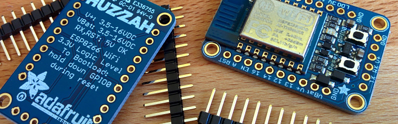
 This board is about 1.5 inches by 1 inch… like two postage stamps side-by-side. It hosts the FCC and CE approved module which we first heard about in December. These modules need a 3.3v supply and there is a regultor on board which can supply up to 500mA (the module can consume as much as 250mA) and can be fed by a battery, USB power, or any other 5V supply. As I mentioned earlier you need to pull a pin low during reset to put the module in programming mode. There are two switches on the board that facilitate this, hold the user button down and press reset and you’re ready to flash.
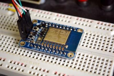
On a breadboard you’ll have two rows not covered by the board on one side, and one row on the other. The board doesn’t have a USB-to-UART bridge but we’re fine with that. On one end of the board you’ll find the common pinout for a USB-to-serial programming cable. Above you can see the programming cable Adafruit sent me with these samples. 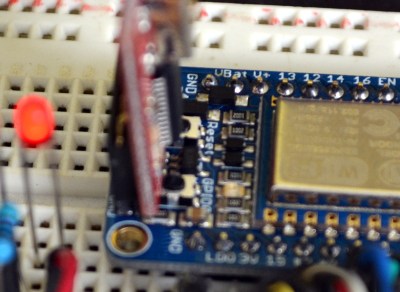 To the right I tried out my 5V Sparkfun FTDI board and as advertised, the HUZZAH can be programmed with either 3.3v or 5V logic levels.
The one thing I noticed is that the two buttons are a bit tricky to get at with the programmers connected, especially the FTDI board. For the second module I may supply my own right-angle header to get around that. Of course doing so would cover part of the breadboard so this is probably six of one, half dozen of the other.
I love it that they supply the pin headers but don’t solder them. Sometimes I prefer pin sockets or unpopulated pads, and this makes it easy for me to make that choice like the right-angle one I mentioned above. It’s something small but I also appreciate that the pinheaders in the package were not the minimum number necessary for this board — there were a few extra pins. You need to break them off and sometimes they can break one pin over from where you expected. If it were the minimum number you would either start over or solder a single pin at the end of the row (not ideal). If you screw up snapping these you could conceivably use a set of three pins and the rest as one unit to fix your mistake. Maybe I’m weird but it’s the small things in life!
Programming Options: NodeMCU and Lua
The board ships with this firmware on it. I was up and running with the Lua interpreter within three minutes of the package arriving at my door. Seriously, it took me longer to figure out if the USB-to-serial was green or white for TX/RX than it did to connect to my local WiFi Access point. Adafuit’s ‘Hello World’ walkthrough gets you going if you haven’t given this a try before.
Programming Options: Arduino IDE
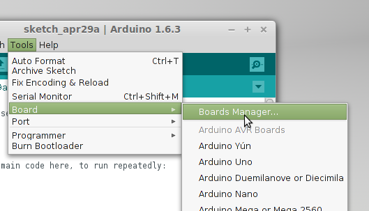 Adafruit has a Board Manager for Arduino IDE. Perhaps this is common knowledge but I don’t often work with this IDE and it’s the first time I’ve run into it. What can I say, it kicks ass!
I hate setting up tool chains for new chips. With this you add a web address and port number, restart the IDE, and use the board manager to add support for this board. Sweet!
That turns this into an Arduino compatible board which solves something that has long bothered me. I’ve seen a ton of really simple Arduino projects that use the ESP8266 externally. Last month’s porting of the Arduino framework for these chips, coupled with this ready-to-go hardware does away with that nonsense. Seriously, the vast majority of those projects need little to no computing power and will work like a dream when directly programmed onto this chip.
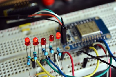 To prove my point, I knocked out this quick binary counter that uses five LEDs as outputs. I’m not leveraging any of the WiFi features on this, but the compiled binary is 174,358 bytes and the Arduino IDE reports this board has a max capacity of 524,288 bytes. It five I/O used for LEDs there are still four more digital pins, the two UART pins, and an ADC input.
Programming Options: esptool
Arduino will overwrite NodeMCU but that’s easy to reflash. I followed [cnlohr’s] direct programming guide to write the binary using esptool. Both this method and the Arduino method are directly programming the EEPROM on the module. This is exactly the same method you’d use if you wanted to develop natively using the Espressif or the Open Source SDKs. Here’s the commands I used to reflash the NodeMCU firmware:
sudo python esptool.py --port /dev/ttyUSB0 write_flash 0x0000 /home/mike/Downloads/nodemcu_latest.bin
Get the NodeMCU binary from their “latest” folder of github repo.
Conclusion
“Buy as many of these as [Phil] will make for us.” That’s what I’ve asked [Julian], the Hackaday Store manager to do. You should be able to get the Hackaday black version of this in a few weeks. Adafruit is currently sold out but I’m sure they’re racing to remedy this.
These are amazing little boards. The price of $9.95 is crazy considering what you get for it. I’m talking about the entire ecosystem which gives you multiple flavors of programming environments. Adafruit has done a lot to contribute to the code and knowledge base here, but a mammoth portion of this is community developed and I think coming in low on the price is one more way Adafruit has chosen to be a good guy in this ecosystem. The board has a ton of I/O for what it is, and if that’s not enough just, implement I2C, SPI, or UART to couple a beefy uC to the connectivity this one brings to the party. I see zero downside on this board. It’s as close to perfect as you can get.


How long until these are ripped off and sold on ebay for even less, original branding intact?
Why would they? Ada is a bit late to the 8266 party, the $10 NodeMCU clones already does everything and has USB.
Ada could have upped their game with at least a larger Flash part, but right now I see another middle of the road breakout board. It’ll probably be more interesting once adafruit.io opens up.
So, which happens first, Ada’s cloud service, or that Oak kickstarter?
Why would they? Because $3 boards sell in larger quantities than $10 boards.
I’m really interested in the Oak.
1) neat gadget.
2) “Don’t want to link to our cloud? K. Here’s the source, roll your own.”
Erik may not have always had the best luck with suppliers, but he makes fun toys.
Shame that the cloners can’t even be bothered to comply with the terms of the license most of the time. It’s pretty permissive, and I don’t see what the downside would be to compliance.
they pretty much just want the brand recognition. Looks betters when it says ‘Adafruit’ than when it says ‘Bobs bargain boards’. a lot of bad clones aren’t even fully functional. Always thing twice before buying knockoffs.
If you always thing twice you’ll have another thing coming.
I know the programming pins are 5V tolerant, but are the GPIO’s level shifted on this board or are they 5V compatible regardless? If no level shifting on board or no 5V tolerance, then FOOEY!
3V3 is still more of a freaking hassle than anything.
Nevermind, its printed right on the board… 3V3 logic…. That sucks… Not the solution for me!
Maybe, just maybe, your eyes would not bleed if you switched to 3V3.
I thought it was nice of Adafruit to put that info on the silkscreen.
5v part needs more then 3.3 volts for input hi?
You can up the voltage to 3.6 and still be in spec.
http://dangerousprototypes.com/2011/04/25/voltage-threshold-chart/
3.3V is 66% of 5V which is the minimal CMOS input threshold for a logic level high. They don’t picked 3.3V out of the thin air…
Most of the TTL families inputs have their VIH around 2V, so they can be driven from a 3.3V output directly. Going from a 5V output to 3.3V requires some level translation.
But seriously the old 74 series was from 1964. With 50+ years of progress, Transition to 3.3V was at least 20 years ago. Probably around time of 68040 or 486 SDRAM days or even earlier. In Moore’s law time frame, that’s well before from the middle ages.
Shouldn’t people be using newer parts at least within that last 10 years ago these days?
I blame USB being 5v for the preponderance of 5v hobbyist parts. You have to admit, it’s really tempting to say “it just plugs into USB for power and you don’t need any regulators or converters or anything.”
Some of us have applications where we don’t get to pick and choose the Vcc or logic level of the stuff were are interfacing to. Some of us have specs we have to follow regardless of if it SHOULD work. Some of us don’t want to start from scratch and completely redesign something to work with 3v3 when just replacing the regulator won’t work. Some things are mixed digital and analog… Some of us have been around before USB was a thing and 5V TTL was as low as you’d see stuff, and trust me, there is A LOT of that stuff still out there. Some of work in electronics professionally and have to deal with all of the above. 3v3 is a headache.
Which voltage regulator IC is used?
It looks like the ESP8266 Breakout Board season has started this spring. It’s raining with them all over the place :)
About ESP8266 Boards, have you seen this one:
http://www.esp8266-projects.com/2015/04/esp8266-ultimate-devboard-finally.html
Something more than a breakout board, full of resources, ADC, DAC, Sensors, etc.
And also looks like is integrated in Arduino IDE :
https://www.youtube.com/watch?v=Z0eTuNmUlRY
Something like that will worth a deeper look from Hackaday guys, what do you think about ?
To me it looks a bit bloated… more of a development platform than a breakout board. I want the WiFi the ESP8266 has in a package that’s easy to prototype with. If I need DACs, displays, and Sensors I already have those on their own breakout boards.
I’m not saying this is bad, I just think it’s just going to have a much narrower pool of users.
Claims:
18 bit ADC
12 bit DAC
Voltage Measurement
Current Measurement
Temperature Measurement
Real Time Clock
High Resolution LCD COG Display with direct sunlight reading
User Definable Buttons
On Board 3.3V Regulator
If is true, not a bad ESP board to play with a lot of things:)
And it look it’s loading the software from Arduino IDE without a touch ?! Do you think this is possible? No reset or programming mode before? Take deeper look a look at the youtube video.
Not to take over the threads here. But I would have gladly paid more for the board had they used the other side with all the silkscreen for a level converter, either IC or discrete and a USB chip. I bet they could have fit those in there. Then it would be “perfect”. I don’t see how it’s different than other boards on auction sites or the site where one HaD staffer sells his version?
Maybe Adafruit will work on a revision that includes the extra parts? I mean, sure I could do my own off-board level conversion, but why include a 3V3 regulator to make it work on a 5V bus and have the programming port be 5 volt tolerant and then force me to do the level shifting and add yet another thing to deal with? It’s a good price, but come-on!?! Sort of half-baked.
I think it’s only half-baked if you’re locked into 5V prototyping. I’ve gone to 3.3v once I started getting into ARM and I’ve never regretted it.
Honestly, 3V3 is not the future, it’s been here as the mainstream for about a decade. Don’t be a fool, move to 3V3 before you look like the guys using transistors and tubes, everything modern sensor or whatever you need is designed for 3V3.
I have been dealing with 2.5V GPIOs on the AR9331 for almost 3 years…
Remember, P = U x I, so one way to reduce power consumption is to reduce voltage… At the expense of noise margin!
I expect to find 1.8V, 1.5V or 1.2V soon.
I have a set of 1.2v EEPROM I ordered by mistake which I’ve been holding onto for years…. waiting for the day that I use that in a design. #TalesFromMyPartsBin
To clarify: Your statement is true, but if you have a 5V or 3.3V or whatever linear regulator on board, and use a linear regulator to a lower voltage (e.g. 1.5V), you’re still burning that power through the regulator. This is why efficient DC-DC buck (or boost, etc) regulators are desirable. Instead of burning whatever current times the drop in the linear, a buck acts like a DC transformer with relatively low losses (depends on efficiency).
Well, I’ve got stuff that isn’t 3.3v that I want to talk to.
Let’s see you do that with your 3.3v stuff.
What kind of ahol comment is that?
Can’t wait until parts only need 1.2V or lower and can run on a single AA battery or a couple of solar cells.
Time to kill of those expensive but crappy capacity 9V battery. They have worse energy/dollar ration in any North America box stores. They only belong in the smoke detectors.
It’s just that all my fixed power supply breadboards are 5 volt.
FYI electrodragon have nodemcu boards (all GPIO broken out with micro USB to UART onboard) for under $10. Should arrive as quick as Adafruit for those of us in Europe.
http://www.electrodragon.com/product/nodemcu-lua-amica-r2-esp8266-wifi-board/#prettyPhoto
They also have breakouts for the $3.50 ESP-12 modules with the 3v3 regulator and the two buttons for $1.60 if you don’t need all the GPIO or USB to UART.
http://www.electrodragon.com/product/esp8266-smd-adapter-board/#prettyPhoto
It’s full of them, all over the place. I was expecting something more elaborate from Adafruit.
Look at the OLIMEX one:
https://www.olimex.com/Products/IoT/ESP8266-EVB/open-source-hardware
Or the one I posted above from esp8266-projects.com:
http://www.esp8266-projects.com/2015/04/esp8266-ultimate-devboard-finally.html
Or this one on Tindie:
https://www.tindie.com/products/Ba0sh1/esp8266-esp-0712-full-io-breadboard-adapter/
Or all the zillions on Ebay and elsewhere…
Didn’t [cnlohr] say a while ago that Electrodragon ships from NJ? So it should be the same shipping time as Adafruit in NA, too.
It’s all well and good, but the power consumption of the esp8266 is astronomical for a sensor node
I don’t consider sleeping @ 78µA “astronomical” for a WiFi sensor node:
http://tim.jagenberg.info/2015/01/18/low-power-esp8266/
Ok, that’s better than I expected, but the convenience of wifi still doesn’t make up enough of a win over BLE chips that average ~15uA overall (including radio traffic) connecting to a BLE-wifi hub – TL-WR703n in my case… :)
TL-WR703n has BLE? Since when? *excited*
So, does this board really have FCC certification? It doesn’t matter if the ESP module itself is FCC certified. In order to transfer the ESP certification into HUZZAH, the former would have to be a standalone module according to the FCC definition, that is: have a fixed antenna, an on board voltage stabilizer a RF shield, I/O buffering and a few things. As far as I know, no ESP module has in-built stabilizer or buffering.
If anyone’s curious, please read page 4:
https://apps.fcc.gov/eas/comments/GetPublishedDocument.html?id=208&tn=830118
Adafruit sells a number of uncertified radio devices, including an earlier version of the ESP8266, as “for hobbyist use only” — I wouldn’t be at all surprised if this is one of them. The little FCC logo means nothing on parts you can buy off AliExpress for a couple of dollars.
Then again maybe Adafruit has gotten their hands on an actual certified model. That’d make this definitely worth the 100% markup over the same part straight from China.
Given Adafruit’s influence and the excellent tutorial I have no doubt this product will bloom.
But as the designer of https://www.tindie.com/products/Ba0sh1/esp8266-esp-0712-full-io-breadboard-adapter/ (also linked above) I would like to give some of my comments.
First is the breadboard real-estate usage. Leaving 2+1 rows at sides is not enough in most of cases. But compare with NodeMCU’s $10 board (which leaves no free rows) this is much better. In my design I managed to free up 3 rows at each side, but the pin header have to be custom made and certainly not for mass production.
Next the regulator. If they really wanted to accept 3.6-16V V+ they should carefully think about the heat dissipation. Just assume input is 5V, and we calculate power dissipation by using the claimed 250mA, that is 0.825W. Give the SOT23-5 thermal resistance without proper PCB heatsink for about 250C/W, the temperature will rise 206.25C!
Thirdly, the GPIO0 push button. The GPIO0 has to seen low potential during reset for ESP8266 to enter bootloader mode. But it doesn’t mean GPIO0 can be shorted to ground all the time.One can simply hook a 1K resistor between GPIO0 and ground, then measure the waveform on GPIO0 side. This pin will continuously output data about 20ms after reset. I’m not sure if short output to ground have and harm to the chip, but I would rather include a resistor for safety.
To be frank I would like to see adafruit to ditch the Chinese modules and redesign the board from scratch. That could overcome many restrictions and that is what hobbyist like me is unable to carry out without commanding power to the manufactures.
Btw, if Adafruit staff is watching, please pay attention to the ESP-12 modules you ordered from Ai-thinker. I have a failure rate of about 2% in my batch of 200 modules. The syndrome being occasional (20-70%) boot failure. Refresh the firmware sometimes helps to fix the problem.
Saying “the Arduino IDE reports this board has a max capacity of 524,288 bytes” isn’t, I don’t think, strictly true, That’s probably what the IDE is set to address by default…
ESP8266 modules are known to come in various sizes of Flash memory, from 1/4MB (ESP-01) to 16MB (the Olimex boards that I have to hand).
It is possible to determine the size of the Flash memory chip that’s fitted (according to posts on forums) but I’m not not sure that actually setting the maximum automatically has been implemented and of course, with everything inside a tin can, it’s impossible to read the markings on the chip to do it manually…
The only thing we need to convert from 5V TTL serial to 3.3V is a single reverse biased diode? How does this work?
Your binary counter required 174 kB?! I think I’d struggle to write a binary counter program for a basic Arduino (ATmega328) larger than about 8 kB. Does the ESP8266 just have a really inefficient compiler?
It seems Adafruit want to make their money on delivery. $16 delivery to the UK for a board that costs $10. No option to send in normal mail. I am happy to wait for the cheap copies from China that will no doubt be delivered either free or for less than $3
Try contacting Proto-Pic – if they’re not stocking it, they’ll orobably order it for you. I find them brilliant.
http://proto-pic.co.uk
can’t get mine to connect to any wifi