
Rice is cultivated all over the world in fields known as rice paddies and it is one of the most maintenance intensive crops to grow. The rice paddy itself requires a large part of that maintenance. It is flooded with water that must be kept at a constant level, just below the height that would keep rice seedlings from growing but high enough to drown any weeds that would compete with the rice stalks for nutrients. This technique is called continuous flooding and a big part of the job of a rice farmer is to inspect the rice paddy every day to make sure the water levels are normal and there are no cracks or holes that could lead to water leakage.
This process is labor intensive, and the technology in use hasn’t changed much over the centuries. Most of the rice farmers in my area are elders with the approximate age of 65-70 years. For these hard working people a little bit of technology can make a big difference in their lives. This is the idea behind TechRice.
TechRice is a project that started as a collaboration between hackerfarm and Digital Garage in Japan. I was contacted by one of the heads of FutureLab, an internal R&D group inside Digital Garage and they were asking me about potentially interesting projects that could be done involving Internet of Things. I’m not particularly fond of the term “IoT” but there are many projects that could be done involving sensor networks that would be useful both in Japan and around the world.
We met up with Digital Garage at their main office in Ebisu to discuss some possible projects. I also ended up talking about hackerfarm, a hackerspace some friends and I set up in rural Japan to focus on agricultural technology and issues that affect the Japanese countryside. One project that came up was rice field monitoring using wireless sensor networks and it caught the attention of some of the members in FutureLab. That’s pretty much how the TechRice project started.
Rice Paddy Sensor Networks Make a Lot of Sense
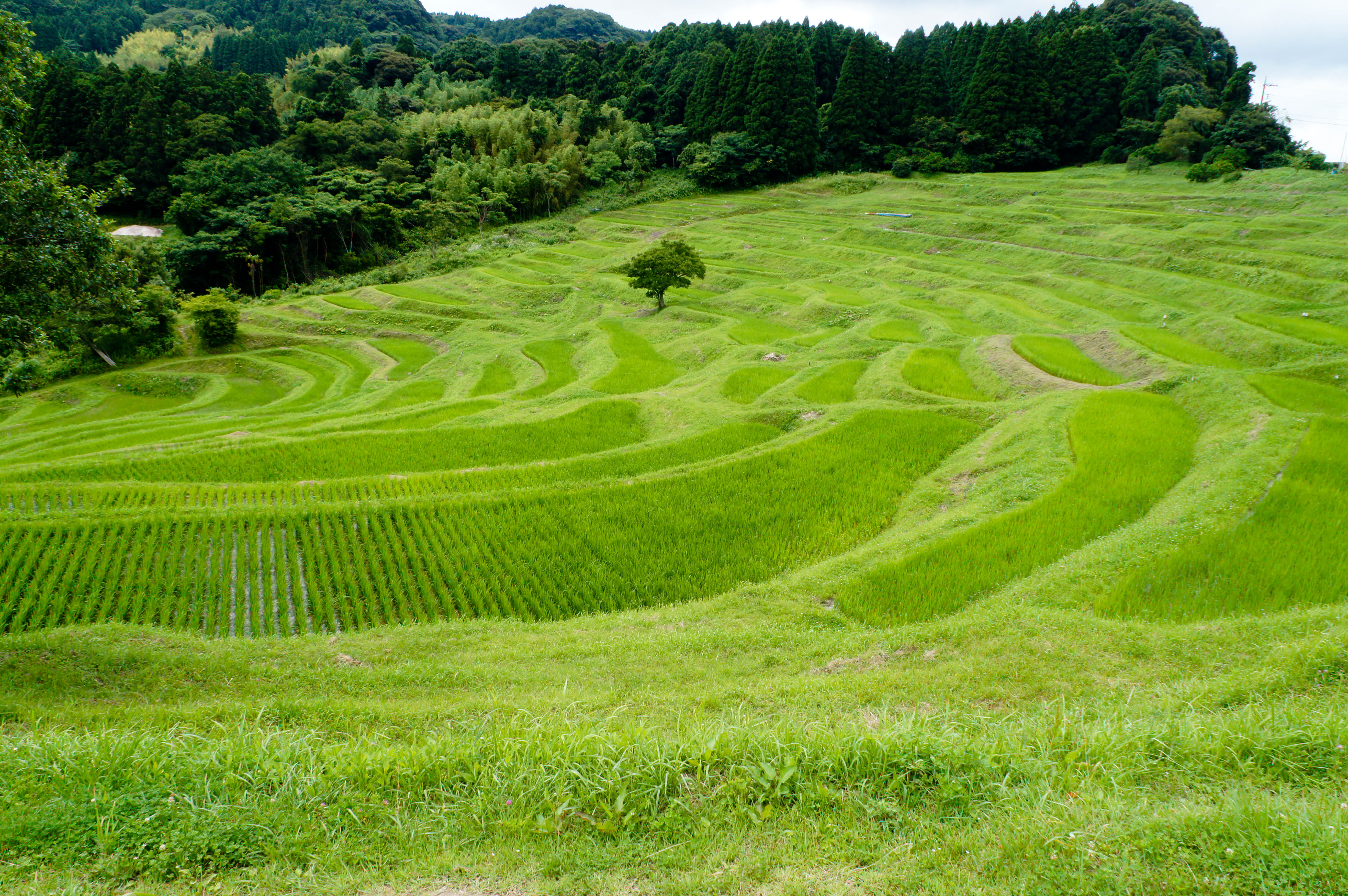
The area around hackerfarm is a hilly rice growing community with many stepped rice terraces. Because of the terrain, the rice paddies can’t grow to be more than a few square meters, approximately enough size to feed one family for a year. There can be as many as thirty rice paddies in one square kilometer, each belonging to different families that own and work them.
The rice paddies are not adjacent to the farmers’ homes so the farmers must travel to the entrance of the rice terrace every day and walk uphill to their rice paddy to inspect it. If there are any problems, they also need to do maintenance on it. As the farmers age, going to the paddy everyday and making the uphill trek to their paddy becomes more difficult. As I discussed various problems in the local community, this stood out as a problem that can be solved with a bit of technical automation. The rough pieces to do this would be a water level sensor, a way to communicate that water level measurement to a server, and a way to visualize the data.
One Simple Board Does it All
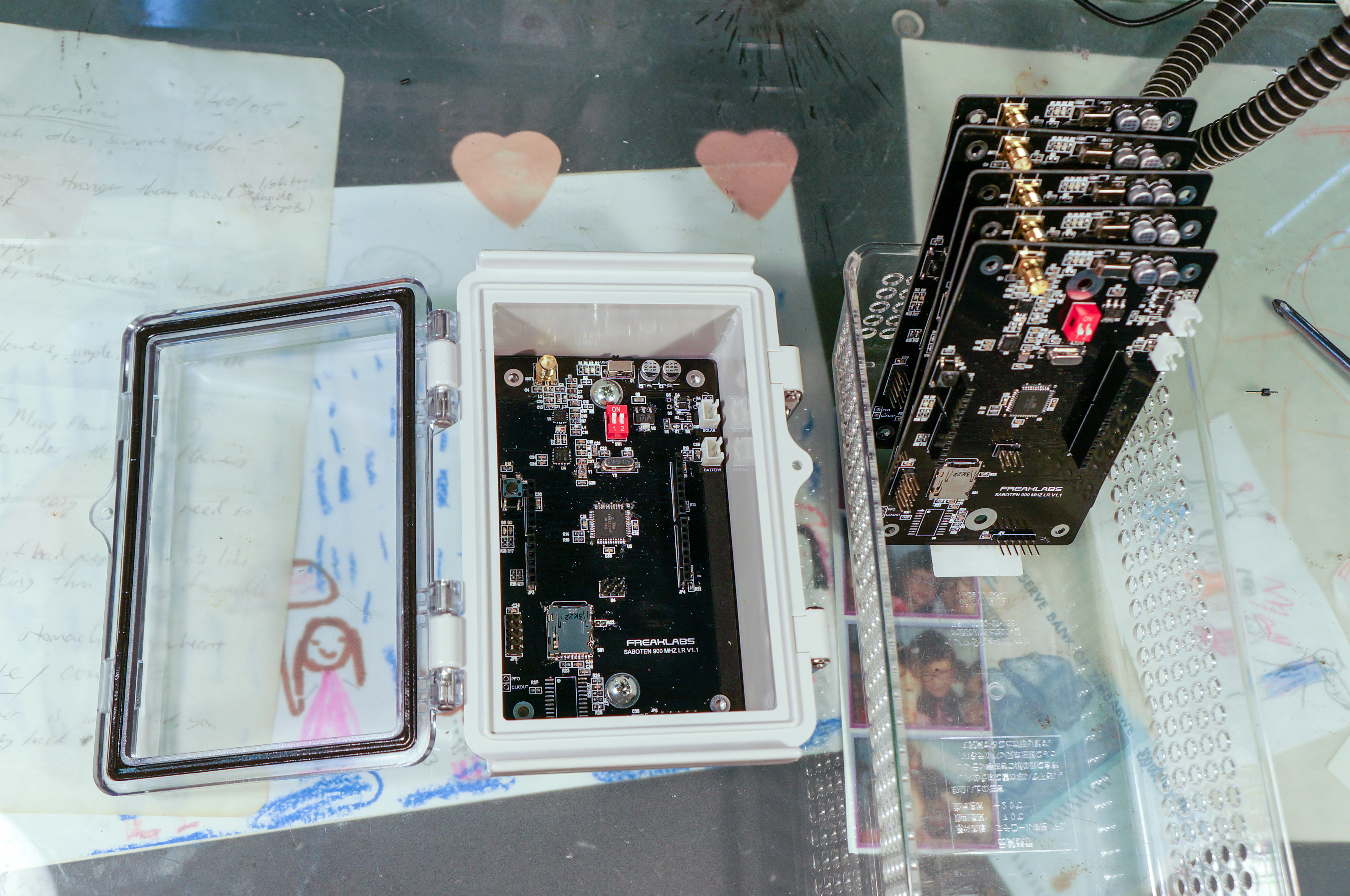 The main sensor node uses a device called “Saboten” meaning “cactus” in Japanese. It’s a device I designed originally for monitoring water levels in large water storage tanks in the Himalayas and also for monitoring mangrove forests in Costa Rica. It consists of a modified Arduino platform based on the ATMega1284P microcontroller. I chose this MCU because it has 16kB of SRAM as opposed to the 2kB used in the standard Arduino MCUs. The RAM goes very quickly since we’re using a FAT32 file system to store data locally on an SD card, as well as assembling long text strings to send to the aggregator. The SD card serves as a local backup for sensor data as well as maintaining a system log for debugging and analysis when the system has issues. I also wanted to stay with the Arduino environment since it’s widely used with a great developer community.
Sensing Water Level in Outdoor Paddies
The main sensor is an ultrasonic acoustic range sensor called MaxSonar by MaxBotix.Acoustic sensors are often used in non-contact liquid level sensing because they don’t have the drawbacks that float or submersion sensors often suffer and won’t risk leaching chemicals into the water. The MaxSonar is essentially an amplified acoustic speaker with a horn attached to focus the ultrasonic chirp in a single direction. We’re also experimenting with building our own ultrasonic level sensor using a waterproof piezo actuator and a 3-D printed horn to see what kind of range we can get. For the rice paddy monitoring, we only need about two meters of range so anything around there would be fine. The MaxSonar has a range of around 10m which is overkill for this particular application.
The front end RF interface consists of a 900 MHz 802.15.4 wireless transceiver with a 500 mW power amplifier on the transmitter and an 8 dB low noise amplifier on the receiver. These were implemented to optimize the transmission range since many applications have the nodes separated by a few km. With proper antennas, it’s possible to send data over ten kilometers so its overkill for the rice terraces which have a diameter of approximately 2 km.
I also included a temperature compensated real time clock on Saboten to maintain an accurate alarm for periodic wake from sleep. In low power sleep mode, the MCU can only be awakened from a few sources, one of which being an interrupt on its IRQ lines. The real time clock can be programmed with an alarm that triggers an interrupt every millisecond, second, hour, day, week, etc. This is a valuable feature for low power applications since the only built-in way to have timed wakeups on the AVR is to use the watchdog timer with a maximum timeout of 8 seconds. This results in a lot of wasted power waking and then going back to sleep again if we desire something like a 4 hour sleep interval.
The RTC chip also has temperature compensation to reduce the amount of clock drift as the temperature varies. This is an important factor to consider when designing devices that will be deployed outdoors and need to maintain accurate time. For sensor networks, accurate timekeeping is essential because we need to align the data from each node and data alignment is usually done via timestamp.
Sipping from Batteries and Using the Sun
One of the biggest topics to consider when developing a wireless sensor node is the power consumption. Many people try to develop a design that has the absolute lowest power consumption possible but this usually requires tradeoffs and contortions to minimize consumption. The Saboten device goes down to about 300 uA in low power mode which is good enough to survive about 9 months on a standard 2000 mAh LiPo battery. Things could have been optimized for lower power consumption but it would require using expensive parts and increasing the complexity of the software, potentially increasing the chance of field failures. Instead Saboten has a built in solar charge controller that was fitted with a 100 mA, 5V solar panel. This is a fairly standard solar panel that can be purchased in the Shenzhen markets for less than a dollar. At an average current consumption of 1mA (active + sleep), a one hour charge in the sun with the panel would keep the system running for ~4 days. In other words, there’s more than enough charge capacity to keep the battery topped up, even if the sun is absent for months.
 There are also some small features I added to help with analysis and system debugging, especially remotely. There is a voltage monitor on the battery voltage and also on the solar voltage. With these two pieces of information, it becomes possible to remotely see if the solar panel is charging the system properly, if the battery is going bad, or if the system is not sleeping as is intended. I like to send power system data along with sensor data so that we can predict when a node is about to go down and also see if there are any power aberrations that correlate with “strange” data. I also fitted the Saboten board to an IP65 weatherproof enclosure with all external cables going to cable glands to maintain the integrity of the weatherproof seal.
The Saboten sensor nodes send all their data to an edge router which is basically a Saboten with a 3G shield mounted on it. The 3G modem is usually powered off and is just turned on twice per day to upload data. It’s a huge consumer of power with a maximum current consumption of 2A at 5V (10W) when it’s just turned on and searching for base stations. We’re currently being very careful with the power consumption on that board but will hopefully be uploading more often as we properly size the solar panels and battery for it.
Firmware, REST, and Python
The firmware is basically vanilla firmware that implements power management and communications via the chibiArduino library. You can get an idea of how the power management and communication code is written by checking out my tutorial published a few years back for the Freakduino. The basic hardware subsystem is the same as my Freakduino boards so most of the code in this project is recycled. But the full device code is hosted on the Digital Garage Futurelab GitHub account.
In my opinion, the more interesting part of the software is the web backend. This part was done by Halfdan Rump at Digital Garage and introduced me to the wonders of Python as a web programming tool. We used Python Flask which makes creating a RESTful API ridiculously easy. The Flask framework also contains database plugins to handle most popular databases so interfacing is also quite simple.
The TechRice API Halfdan wrote is called the Satoyama API and handles standard CRUD operations in a RESTful way. The data is exchanged via JSON messages uploaded to a server housed on Heroku with a Postgre database. Data is collected by each of the sensor leaf nodes and sent to the aggregator node which is the edge router with the 3G modem. The 3G modem is fired up twice a day to upload the data via HTTP to the Satoyama server which will update the database entries. Once the data is in the database, the data is available to be consumed by either the mobile app or to be displayed on a web page.
Just a word of warning. The code and hardware is still a work in progress so it changes frequently and goes up and down all the time.
The Network Topology
Network topology is an interesting topic for people involved in sensor networks. I was originally a fan of meshing networks but since I’ve had a few real deployments already, I’ve come to prefer single hop networks. In this case, I’m using the chibiArduino wireless stack to implement a single hop link to the aggregator node. With the amplified RF front end, the range is no problem at around 1.5 km in mainly open field. In general, I prefer to stay with single hop links whenever possible and vary transmit power and antenna gain instead. Keeping the network simple means there’s less of a possibility of the network going down which also means I don’t have to keep going out in the field to troubleshoot network issues.
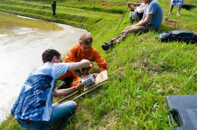
Literal Field Tests and Literal Debugging


The project was deployed this year during the rice planting season and we collected initial data which was successful but also pointed to some holes in our logic. There were some incorrect assumptions on the power management and we mainly need to make the system more robust. Out in the rice paddies, there are all kinds of insects that will happily crawl into any hole or crevice available which also includes the acoustic sensor’s horn. That’s one reason we’re experimenting with creating our own sensor which could also be made insect proof. Otherwise, it’s mainly an iterative process of improving the hardware, software, fixing bugs, and making the system robust enough that it can be deployed in more remote locations and have a high uptime.
From Monitoring Paddies to Tracking Wild Boar
We’re hoping to have the system fully online for next year’s rice planting and also extend it to other applications such as boar trap monitoring. Wild boar are an invasive species in Japan and are considered a huge pest since they can decimate a farm in a single night. Boar traps are set up around the area but many of the trappers are older and can’t police the traps all the time. We’re going to adapt the system to notify trap owners whenever a wild boar is caught.
We’re also working with a group called TechAguru in Balanga City in the Philippines. TechAguru is an offshoot of the Balanga makerspace in rural Philippines and their focus is on optimizing the rice farming process out there. John Auxilios, one of the founders of TechAguru, came out to hackerfarm this year to discuss their project and we’re planning to bring the system out there and collaborate with them on rice farming in the Philippines. Otherwise, we’re mainly hoping to get the system ready for primetime and do an open source release soon :)
The TechRice Team
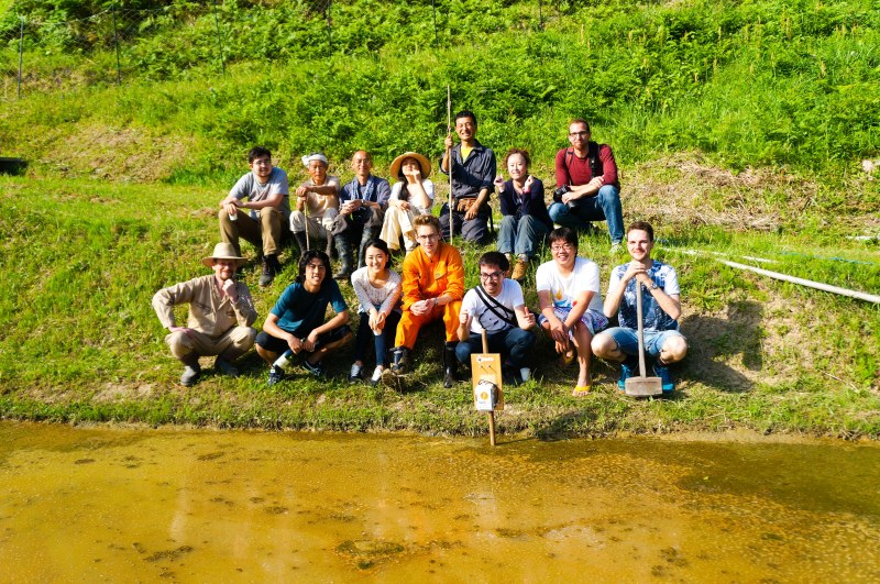
The main TechRice team consists of a hardware engineer (Akiba), a firmware/embedded engineer
(Masa), a frontend/backend web programmer (Halfdan), a mobile/data visualization programmer (Yuta), and other engineers that assist with various tasks associated with the project. One of the complexities of the project is that wireless sensor network deployments require specialists from multiple domains. A lot of specialty hardware is needed to meet power and communications requirements, firmware to run the individual nodes, web backend programming to implement the web services and REST API, and front end data visualization for web and mobile presentation. I think we’re extremely lucky that between us, we have all the experience we need to implement a project like this.


Enjoyed the read. I look forward to looking at the code a little more for working on my own sensor networks.
Yes, please! :) As Akiba said it’s still a work in progress, so when you spot something that is broken or that you think can be improved upon please don’t hesitate to let us know!
Also we have the REST API up and running at satoyamacloud.com, so if you want to post your data there you can do that!
I also wrote a command line tool for interfacing with the database. You can pull it from here: https://github.com/DgFutureLab/satoyama-konohana
Documentation is probably not quite up to speed, so just ask me or another team member about stuff if you’re in doubt :).
Nice work! Interesting choice of a network setup – love it and the project is well detailed as well….in some aspects anyways. I only browsed it over though so i may be wrong
Heh, the docs could definitely benefit from a look-through. But Akiba’s article nailed down all the important things. If you feel like trying the system in action I’d love to help you to get started :).
What a nice work and article. I really enjoyed reading. Hope to see full system working next year.
For wild boar detection, how about to use RPi with IR camera or cheaper microbolometer and point some laser (green ??) /light in its direction to scare it? – Just an opinion.
Yet another Arduino “programmer” who doesn’t understand the fundamentals.
“the only built-in way to have timed wakeups on the AVR is to use the watchdog timer with a maximum timeout of 8 seconds. This results in a lot of wasted power waking and then going back to sleep again if we desire something like a 4 hour sleep interval.”
Waking up to increment a 32-bit counter takes 50-100 cycles.
http://nerdralph.blogspot.ca/2014/07/writing-avr-interrupt-service-routines.html
If the AVR is running at 8Mhz, and waking up every second, that means it is sleeping 99.999% of the time. With the AVR using ~1000x as much power while active, the waking power use is still around 1%.
I suggest being a little more reserved in passing judgement. Akiba is an experienced and respected engineer. Waking up to increment that counter is still a wake up from sleep and still burns power.
:)
Unthinking respect for authority is the greatest enemy of truth. – Einstein
Sorry, but 50-100 unneeded cycles are still wasted energy. Since you need an RTC anyways, why not use the features properly?
Because arduino.
You are moving the goalposts – a classic logical fallacy. Competent programmers remain logical and don’t get defensive/emotional.
And you don’t need an external RTC. Another example of how you are not so competent.
http://petemills.blogspot.ca/2011/05/real-time-clock-part-1.html
Let’s see..
Watchdog timer of an AVR can be setup to overflow every 8 seconds.
There are 86400 seconds in a day, which means the AVR will approx. wake up 10800 times a day.
Seeing as there is only one crystal which is probably reserved for the RTC it’s safe(?) to assume the AVR is running
on it’s internal 8MHz RC clock.
To wake up from deep sleep and increment a 32 bit counter takes 50~100 cycles so the AVR uses between:
10800 wakeups * 50 cycles = 540000 cycles
10800 wakeups * 100 cycles = 1080000 cycles
Divide that by the clock speed of 8 MHz:
540000 cycles / 8000000 Hz = 0.0675 seconds per day awake
1080000 cycles / 8000000 Hz = 0.135 seconds per day awake
AVR uses 4.5mA @3.3V with RC clock.
Which amounts to an average (wasted) current of:
(0.0675/86400) * 4.5mA = 3.52pA
(0.135/86400) * 4.5mA = 7.03pA
Which admittedly is neglible. (and doesn’t even take disabling the ADC in account)
Granted if a RTC is necessary for time stamps then it doesn’t hurt to hook it up to the AVR but otherwise it’s using more energy then it would without.
Regardless it’s a very nice project that contributes to people’s lives and any small technical oversight should not be an excuse to jump on the ‘hurdur arduino’ bandwagon.
Stating that the RTC will lead to decreased power consumption is false if it’s only purpose was to wake up the AVR, however it’s also being used to time network data:
“For sensor networks, accurate timekeeping is essential because we need to align the data from each node and data alignment is usually done via timestamp.”
As such it’s not even a technical oversight though this sentence should be changed as not to misinform people:
“the only built-in way to have timed wakeups on the AVR is to use the watchdog timer with a maximum timeout of 8 seconds. This results in a lot of wasted power waking and then going back to sleep again if we desire something like a 4 hour sleep interval.”
And accurate timekeeping can be done on the AVR. See my previous link to Pete Mills’ blog.
Whether or not a RTC is strictly required or not (although the fact that waking up every 8 seconds does indeed burn more power than using an RTC is indisputable), I think it’s not very constructive to focus on a relatively minor detail such as this.
In general I think that people will be more inclined to take your opinion into view if you go about stating it in a polite way. :)
I don’t give a shit what people think about my opinions. Facts are facts.
I just checked the DS3231 power draw – 840uA. That’s about the same as an ATMega328P @3V in sleep mode.
https://www.sparkfun.com/tutorials/309
Awesome article and great to hear about the projects progress!
Thanks, Nava. Missing you on this project :)
Hear, hear!! :))
Single hop network? Argh. It’s 2015. Wireless sensor networks were supposed to be a golden technology that would bring data ubiquity throughout the world. And, still, there’s no good universal solution.
Anyhow, this stands as a fine example of the incredible amount of engineering and expertise it takes just to get data exfiltration from a network of static sensors.
Heh, you know what, that’s exactly what I thought when I started working on the project. I was like “OMG mesh is so cool, I wanna do that!”. But actually using a star topology is quite powerful, just as Akiba says. And the tradeoff between implementation complexity and robustness is not a huge deal I think. Even if the edge node gets fried by lightning or something like that, all the data is retained on SD cards in the sensor nodes.
But yeah, it’s not impossible that we’ll look into mesh in the future, although personally I would like it to wait a bit, heh. :)
Have you looked at OpenWSN? They were the “chosen one” of the WSN world, coming out of Kris Pister’s lab. He invented TSMP/TSCH , and OpenWSN has been a huge development effort to implement that project. They are working very hard on routing right now. And I don’t think their software API is anywhere near as slick as a RESTful, database driven model.
You could also just look at Dust Networks, now owned by Linear systems. They have a single chip that just outright gives you a super reliable, low power network: http://www.linear.com/product/LTC5800-IPM
at only $20 – $50/chip!
Designing your own level sensor for this sounds like an interesting problem. I might try playing with making a depth stick with stainless steel bolts at set lengths and throwing different value resistors on them in a voltage divider setup and having the mcu read the level… It would be simple and robust (ish). I’m not sure you wouldn’t get any galvanic corrosion on the bolts with running even a bit of electricity through it (doubt it would), but it might be interesting. I thought of doing something similar with an aquaponics bed to shut down the system if leaks develop.
The problem is that we can’t risk leeching any chemicals into the rice paddy so everything has to be non-contact. All of the rice paddies are for organically grown rice.
Non-contact is the way to go then for sure.
Nice write up, btw.
Also the mean time to failure for the transducers we’re using is rated at 50k hours :D
Are there any acceptable materials that can go into the water of the paddy? Are copper wires not allowed? I was thinking along the lines of level sensors for a low/high alert (not sure of the tolerance of the rice plant) with wires placed inside a bamboo pole. Holes in the bamboo allow contact with the wire, resistance changes, level is determined as either high or low. Reaction time wouldn’t be immediate, but I would expect an alert within minutes of water level dropping or going high. Wiring for the sensors would exit the top of the pole and be connected to the sensor net.
Another thought. Similar to how washing machines determine water level. Utilize organic pole (again assuming bamboo if that’s viable) and use water height to adjust pressure switch that is well outside the water zone. This again would be a high/low design, but all non-organic materials could be kept out of the water area.
Generally speaking, the device has to survive typhoons and wild boars and the like, so keeping it mechanically simple (such as a sturdy enclosure on a pole) is an important design factor.
The installation needs to be sturdy and mechanically simple to withstand typhoons and large wild boars and the like, so I think the existing configuration of a sturdy waterproof enclosure on a stick, no contact, and no moving parts is best.
You’re saying that using bamboo tripods with a simple pressure switch within one of the legs and the remainder of the device on top of that tripod would be any less stable than what they’re doing? Sometimes the simplest method is the right answer. Don’t overengineer what can be done with simple switches.
It will not be reliable at all, you get galvanic corrosion (except with gold), contamination of probes in the long run.
One way not very often used is to have capacitive sensors, they can also be used as humidity sensor.
I didn’t know about capacitive sensors for measuring humidity. Thank you for the tip!
It sounds mostly like discreet and mechanical problems that require lab testing. Get rid of string modulation and FAT32?
Aww, don’t be hating FAT32 >,< :P
Use one of those fancy embedded file systems optimized for write-cycle efficiency
So how does the cost of this system (including the maintenance, monitoring devices, etc.) compare to the annual income of people doing rice farming in subsistence agriculture?
(i.e. is this affordable/cost effective)
That’a a good question. But we aim to keep the system as simple and cheap as possible, something which Akiba is an expert in doing. :)
Did you already see any correlation between your wireless link quality / packet reception ratio and humidity? I read a lot conflicting info in papers about deployments where fog over a field improves the communication or just makes the PRR go to 0. Lower frequencies seem to deal better with high humidity though (900MHz vs 2.4GHz).
Must say I’m not familiar with Japanese weather, maybe humidity is at 100% all the time and you don’t really see any changes.
I’d guess humidity is pretty high over a paddy field!
All I have to say is great project! It’s nice when a set of brains can come together to invent a new thing, to solve a problem nobody’s addressed before.
Thank you Greenaum!!
Hey Jelmer. No, I haven’t noticed anything like that. But thanks for mentioning it. I’ll definitely keep that in mind if we start running into transmission issues. And we’re recording the data on SD cards, so if there’s a correlation we should be able to see that :).
however, one thing that is not lacking in most of the heavy rice growing parts of the world, is manpower.
Except in Japan actually. The population is aging and it seems that not so many young people want to become rice farmers.
hi I am Joseph Sandro from the Philippines. I am very interested with what you are doing. I am involve in rice research and working at International Rice Research Institute. I would like to be engage on your partner here in the Philippines, the TechAguru. Please contact me through email. j.sandro@irri.org