If we have to make a list of Projects that are insane and awesome at the same time, this would probably be among the top three right up there. For the past few years, [James Newman] has been busy building Megaprocessor – a huge micro-processor made out of transistors and LED’s, thousands of ’em. “I started by wanting to learn about transistors. Things got out of hand.” And quite appropriately, he’s based out of Cambridge – the “City of perspiring dreams“. The Why part is pretty simple – because he can. We posted about his build as recently as 10 months back, but he’s made a ton of progress since then and an update seemed in order.
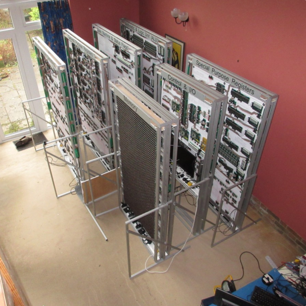 How big is it ? For starters, the 8-bit adder module is about 300mm (a foot) long – and he’s using five of them. When fully complete, it will stretch 14m wide and stand 2m tall, filling a 30 sq.m room, consisting of seven individual frames that form the parts of the Megaprocessor.
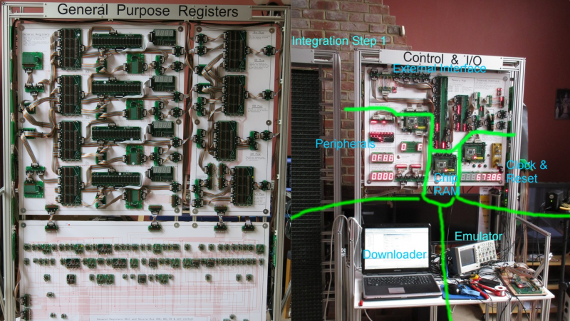
The original plan was for nine frames but he’s managed to squeeze all parts in to seven, building three last year and adding the other four since then. Assembling the individual boards (gates), putting them together to form modules, then fitting it all on to the frames and putting in almost 10kms of cabling is a slow, painstaking job, but he’s been on fire last few months. He has managed to test and integrate the racks shown here and even run some code.
The Megaprocessor has a 16-bit architecture, seven registers, 256bytes of RAM and a questionable amount of PROM (depending on his soldering endurance, he says). It sips 500W, most of it going to light up all the LED’s. He guesses it weighs about half a ton. The processor uses up 15,300 transistors and 8,500 LED’s, while the RAM has 27,000 transistors and 2,048 LED’s. That puts it somewhere between the 8086 and the 68000 microprocessors in terms of number of transistors. He recently got around to calculating the money he’s spent on this to date, and it is notching up over 40,000 Quid (almost $60,000 USD)! You can read a lot of other interesting statistics on the Cost and Materials page.
And kudos to his crazy Ninja skills to notch up just a few failed, bad solder joints, out of a total of over 250,000, and one dead transistor from among almost 42,000. A few cable crimping issues were the least of his troubles. The worst part was when he received a wrong batch of 4000 transistors (correct purchase order, correct packing list, but wrong parts bagged). He realized the problem after soldering all of them, setting him back by quite a bit. He didn’t bother de-soldering them but instead just built fresh replacement boards. He also built a hardware/software simulator for the Megaprocessor using an FPGA board to help him validate his design. Among the first programs he created were a few games (obviously) – Tetris, Tic-Tac-Toe, Life – for which he needed a suitable input device. So he modded a Venom Arcade stick which usually expects itself to be connected to a PlayStation via USB. He says it was “a very civilized thing to mod”.
There is a LOT more interesting stuff to read on his detailed blog posts, so go grab a supply of Coffee, switch off your Phone, and settle in for a few hours diving in to his crazy-awesome build. “This is nuts” said [Clovis Fritzen], who sent in this tip via the BBC News website. Thanks, and we’d agree with his assessment. Check out a couple of videos of the Megaprocessor in action below.


Insane! (in a good way)
Rule of thumb:
between 9 and 1000mm you use cm unless you care about the precision.
Chinese style has taken over. cm have been deprecated.
9mm= 0.9cm
better to begin at 10mm
which is why they wrote between 9mm and 1000mm. that range only includes 10mm to 999mm.
9.01mm, 9.02mm, 9.03mm, 9.03850930842038mm, etc…
“unless you care about the precision”
cm is generally deprecated, since it harks back to the CGS system. It’s perfectly okay to use for daily use, but SI prefixes go in factors of 3.
Deine Mutter is deprecated.
Centimetres are in use wherever designers don’t care about/need smaller units. Arxhitecture is a great example.
Like, for instance, with Intel’s 8.086k processor. (What! We really did call Motorola’s CPU the 68k)
For sure. Now let me go grab my 3.5 cm camera.
Are you planning to release a 1.6cm movie of this event?
Do a recording of 22,86cm Nails concert.
Or is it 0.75ft Nails?
I’ve just measured the containers I used and reckon I possibly got through about 12 pints of transistors.
One of the best concerts I ever saw… And to make it pertinent to the discussion, the opening act was “A Perfect Circle”
Great work. But “””256bytes of RAM … The processor uses up 15,300 transistors and 8,500 LED’s, while the RAM has 27,000 transistors and 2,048 LED’s.””” For each bit you need 2 transistors, so 16 per byte. So it appears that ~4000 transistors would have been enough for the RAM.
Here’s what [James] writes about the Memory cells : http://www.megaprocessor.com/GBU_sram.html
“I use an average of just over 11 transistors per RAM bit. Wikipedia (and most other sources) say the normal answer is 6 with 4 being possible.
When looking at the various diagrams of 6T cells I wasn’t confident I fully understood what I was seeing.”
Hmm. https://en.wikipedia.org/wiki/Flip-flop_(electronics)
I think I’d have spent the effort understanding flip-flops rather than implementing a completely new type with 11 transistors, then paying for and soldering thousands of them. If I wasn’t confident I’d build 1 or 2 on breadboard and dick about with them til it clicked.
That said, I don’t have 40 grand worth of transistors in my bedroom, so he’s got me beat there.
The wikipedia page Miroslav references does show a 2 transistor bistable but the minimum I could find that was usable as the core of an SRAM cell was 4. Essentially an SR latch (which takes 4) of some form. Try https://en.wikipedia.org/wiki/Static_random-access_memory. What I kept banging my head on is that if you start with an SR latch you’ve only just begun. You need to generate Set and Reset signals. Roughly an AND gate or something for each so another two 2 transistor gates and we’re upto 8.
Now we need to multiplex these cells together. I’m sure there’s better ways than I chose but you’ve still got to spend something. I went from a sledgehammer safety approach because I’d had some bitter experiences. (In my research I had also came across other people who had hit similar problems with non-ideal transistors.)
In the diagrams for 4T and 6T cells on the Wikipedia page they use byte and bit control lines rather than generating individual Set and Reset signals which will be much more efficient than my approach. But as I wrote I could not be sure I understood what I was looking at and I struggled to find a circuit anywhere using real components (i.e. with part numbers) and which had a similar control mechanism.
The (huge) count of 11 comes from bolting together standard gates with an eye to safety. I knew it would work and I didn’t believe there was much chance of coming up with something dramatically smaller. So I just bit the bullet and got on with it.
I checked my Malvino&Brown book. SR latch needs only two transistors. Only downside is potential race condition if both inputs are 1 at the same time:
Hopefully this link will work: http://imgur.com/rvnBrw1
I take your point, it’s likely I missed a trick or two on the way. I’ll add something about this to my page.
I don’t suppose your book has a 2T SR latch using FETs rather than BJTs. As I observe at the bottom of page http://www.megaprocessor.com/GBU_DTL_TTL_CMOS.html as far as building by hand is concerned I thought resistors as costly as transistors. In terms of board space and number of joints I have to solder the circuit you give is the much the same as (if not a tad bigger than) my 2 NAND SR latch using 4 transistors and two resistors.
There’s still the question of how to cheaply generate the set and reset signals, and to mux together the outputs of the SR latches.
@ [Miroslav]
True a SR latch only needs two transistors but SRAM is made from D Q latches (data).
In any case real SRAM can’t use resistors and the method mentioned can, so the complementary transistors in real SRAM can be replaced by simple resistors and that will bring the count down a lot. Perhps down to 3 by using a modified SR latch.
Memory is a D Q latch (or data latch) the two transistors will give you the bi-stable latch at the center but them you have to get the data in and requires more transistors.
Some of the methods mentioned have a higher transistor count due to a totem pole output. The totem pole could be moved to the data bus so that you don’t have it on every cell.
*Normal* memory has more transistors because you can’t have resistors as a component. I could imagine a three transistor memory cell using a bi-stable latch (two inverts) and a third transistor to drop out Vcc as the active low write signal.
Can someone hand me the pieces of my brain? Because it just blew up….. oh em gee.
Just for reference, the IBM 7090 used about 50,000 transistors in its CPU.
But it was an industrial build not an individual effort.
And they knew what they were doing.
I didn’t. Not when I started. The whole project started as a learning exercise http://www.megaprocessor.com/GBU_evolution.html . If I were to start again now I’m sure I could halve the number of transistors (probably even keeping the LEDs) in the processor so maybe all I really needed was about 8000 or so.
But I’m never ever ever going to do something like this again.
* LEDs
I came here for this.
So. Much. Blink! Totally awesome!!
Glad to see the British eccentric is alive and well. We should all be this barmy! The world would be so much fun. :)
Ace.
Insanity defined!!!
But seriously totally awesome and beyond me ever doing, my brain would seize.
All those LEDs give it a 1970s Sci Fi look.
YOU HAVE DONE EXTREMLY GREAT JOB,. KEEP IT UP.
There is a level of insanity for which the only valid response is awe.
Now build it with wire wound nail relays, stained glass lenses with little incandescent bulbs behind them, and Crooke’s radiometers for signal detection. Thus getting rid of those solid state devices or even vacuum tubes (which are much more difficult to make than light bulbs). Transistors. Hah! Cheater.
lol, I used to work in a three story relay operated computer. Relays as binary. They didn’t have the flashy lights though.
Anyway, go to yourtube and you will find lots of relay operating Logic / Computers / CPUs. They all fit into a previous;y undefined level of insanity. Relays are quite good for this as they naturally have a binary state.
What did the computer do, just out of interest? Who owned it? Wasn’t Konrad Zuse I suppose.
Um, I probably wasn’t working there in the 1940s lol.
It was a part of a communications infrastructure that dealt with routing long distance calls.
I know that doesn’t sound much like a computer but how much can you expect from relays and technically it was a computer – Turing complete, though it was programmed to operate as a complex state machine.
Now someone needs to clone his architecture in Verilog and put it in an FPGA.
he already did that. for testing. it’s in the post
Probably fits into a CPLD.
It used about half of a Lattice MachXO2280.
I’ll be uploading the code (and all the software models as well) at some point. But there’s a lot of documentation to get write first. And of course I have to actually finish the machine as well.