If you build electronic circuits on a regular basis the chances are you will have used capacitors many times. They are a standard component along with the resistor whose values are lifted off the shelf without a second thought. We use them for power supply smoothing and decoupling, DC blocking, timing circuits, and many more applications.
![Different capacitor applications. By Elcap (Own work) [CC0], via Wikimedia Commons](https://hackaday.com/wp-content/uploads/2016/06/capacitors-overlapping-applications.png)
Back to Basics
It’s best to start with the basics, and describe capacitance from first principles before looking at real capacitors. An ideal capacitor consists of two conductive plates separated by a non-conductive dielectric. Charge can accumulate on the plates, but can not flow between them because of the insulating nature of the dielectric. Thus the capacitor can store the charge.
Capacitance is measured in farads: a one farad capacitor maintains a voltage of one volt when it holds a coulomb of charge. A farad is like so many SI units, rather impractically sized, so outside the narrow realm of supercapacitors which are beyond the scope of this article you are more likely to encounter micro-, nano-, or picofarads. You can derive the capacitance of any given capacitor from its dimensions and the properties of its dielectric using a formula which it’s probably worth sending you to Wikipedia for if you are interested. You don’t need to memorise it unless you are studying for a high school physics exam, but it conceals one important point to take away. The capacitance is proportional to the dielectric constant εr of the dielectric being used, which has given rise to a wide variety of commercially available capacitors using different dielectric materials to achieve higher capacitance ranges or better voltage handling characteristics.
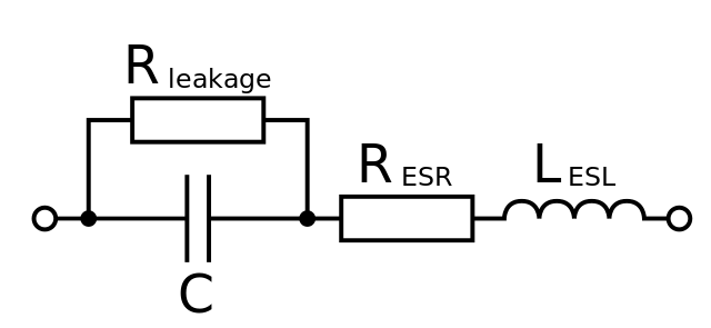
There is a snag to using dielectric materials in a capacitor, along with the desirable characteristics of a dielectric come a host of annoying side-effects. All real-world capacitors have internal parasitic resistance and inductance, and though tiny, they can sometimes have an effect on the capacitor’s operation. Dielectric constants can vary with temperature or voltage, piezoelectricity, or noise. Different types of capacitor can have alarming failure modes or even just be eye-wateringly expensive. And so we come to the main part of this piece, the section in which we’ll take you through some of the capacitor types you may encounter, and lay out for you their various properties both good and bad. We won’t claim to cover every possible capacitor technology, however we’ll run through the common capacitor technologies and examine any subtypes you may find.
Aluminium electrolytic
![A typical small aluminium electrolytic capacitor. By oomlout [CC BY-SA 2.0 ], via Wikimedia Commons](https://hackaday.com/wp-content/uploads/2016/06/cape-th-x-uf470-va_16236695369.jpg?w=400)
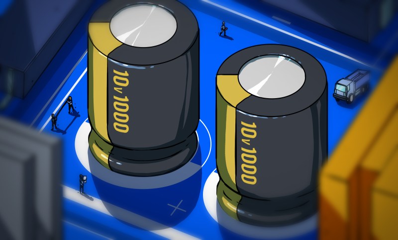
Practical electrolytic capacitors have their plates in the form of an aluminium foil sandwich rolled into a cylinder and housed in an aluminium can. They will have a quoted working voltage that depends on the depth of the anodised layer.
Electrolytic capacitors have the highest capacitance of the types you will encounter in normal use, ranging from around 0.1 to many thousands of µF. Because of that tightly coiled electrochemical cell they have a high equivalent series inductance, so they are not suitable for use at high frequencies. You will typically find them used for power supply smoothing and decoupling, as well as for coupling at audio frequencies.
Tantalum electrolytic
![A surface-mount tantalum capacitor. By Epop [Public domain], via Wikimedia Commons](https://hackaday.com/wp-content/uploads/2016/06/618px-cms_tantalum_capacitor.jpg)
Tantalum capacitors are available with values from around 0.1 to several hundred µF. They have a much lower leakage resistance and equivalent series resistance than their aluminium counterparts, so you will find them in test and measurement, high-end audio, and in other applications where those properties are advantageous.
Tantalum capacitors have a failure mode to watch out for, they have a reputation for catching fire. Amorphous tantalum oxide is a good dielectric, while the crystaline form of tantalum oxide is a good conductor. Mistreatment of a tantalum capacitor by for instance applying too much inrush current to it can cause the dielectric to change from one form to the other, causing a huge increase in current through the capacitor. Happily not all the news is bad though, their reputation for fires came from a much earlier generation of tantalum capacitors, and improved manufacturing techniques have delivered a much more reliable product.
Polymer film
![A variety of film capacitors. Elcap [GFDL], via Wikimedia Commons](https://hackaday.com/wp-content/uploads/2016/06/640px-wiki-folkos-p1090317-1.jpg)
Polypropylene capacitors are used in circuits that require good temperature and frequency stability. You will also find them used in mains suppression and other power circuits, in specially rated versions for high voltage AC use.
Polyester capacitors do not possess the temperature and frequency characteristics of polypropylene, however they are cheap and can withstand the elevated temperatures of SMD soldering. You will thus find them used as general purpose capacitors in non-critical applications.
Polyethylene naphthalate capacitors yet again do not have stable temperature and frequency characteristics, but they can withstand much higher temperatures and voltages than polyester.
Polyphenylene sulphide capacitors possess all the temperature and frequency stability of polypropylene with the bonus of being able to withstand high temperatures.
You may also encounter polycarbonate and polystyrene capacitors in older equipment, however these two dielectrics are not commonly used today.
Ceramic
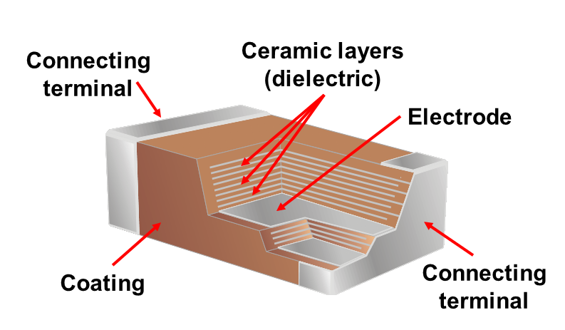
When looking at ceramic capacitors it is best to consider them by the ceramic dielectric used, as it is from these that they derive their properties. Ceramic dielectrics are classified with a three-letter code denoting their temperature range and temperature stability, and it is by these codes that we’ll refer to the most common ones here.
C0G dielectrics have the best stability of capacitance with respect to temperature, frequency, and voltage. You will find C0G capacitors used in resonant high frequency and other high performance circuits.
X7R dielectrics do not share the temperature or voltage characteristics of C0G, and thus are used in less critical applications. You will typically find them used for decoupling and general purpose applications.
Y5V dielectrics give a much higher capacitance than X7R, but with worse temperature characteristics and a lower maximum voltage. Like X7R you will find them in general purpose and decoupling circuits.
Since ceramics are often also piezoelectric, some ceramic capacitors also exhibit microphony. If you work with high voltages and audible frequencies, for example in the world of tube amplifiers or electrostatics, you may sometimes be able to hear this effect in action, as a capacitor may “sing”. If you use a piezoelectric capacitor to provide frequency stability you may thus find it is modulated by the vibration of its environment.
As we stated earlier, this article does not attempt to cover all capacitor technologies. A quick glance at an electronic supplies catalogue will show you several technologies not mentioned here, and there are multiple others that are obsolete or whose niche is so tiny that you will rarely see them. Instead what we hope to have achieved is to have demystified some of the common types you may see, and aided you in your selection when you produce your own designs. If we’ve whetted your appetite for more component rundowns, perhaps we can draw your attention to our piece on inductors.


Never mind capacitors that need almost zero inductance for use in the microwave region.
How about the gimick capacitor? http://213.114.136.42/begin/gimmik-0.htm Or the PCB capacitor? http://213.114.136.42/use/tuning_caps2.htm Variable PCB capacitor? http://213.114.136.42/use/tuning_caps.htm
Yah, I know.. “this article does not attempt to cover all capacitor technologies”. I just thought those would be fun to point out since you can make them yourself!
LOL, no that is fine they are useful links, not sure if his book list any other uses for large capacitors….
Thanks for the link to the variable PCB capacitor. This will come in handy.
I enjoyed those links. Thanks for sharing them.
No mention of the Capacitor plague:
https://en.wikipedia.org/wiki/Capacitor_plague
Jenny forgot to mention that magic blue smoke is inside them too.
Nah, it’s rapid magic blue smoke. It escapes way faster than regular blue smoke.
Thanks for the info! Didn’t know that at all (always thought the cases which I’ve seen were related to wrong temperature specs)!
Especially worthy to read is the root cause of that huge issue: A perfect example for “the good, the bad and the ugly” – the involved Japanese, Chinese & Taiwanese capacitor companies. Perhaps that was the reason why the power unit of my 2006 iMac failed…
Fascinating! I was aware of that issue but had no idea there was such a thorough understanding out there. Thanks for linking us in.
Trap for young players is tantalum’s MANDATORY voltage derating…. which is frequently not mentioned until after your parts fail and the manufacturer points you to a white paper.
http://dkc1.digikey.com/US/en/TOD/Kemet/tantalumcapacitors/tantalumcapacitor.html
Many other traps for the curious:
– Ceramic cap capacitance changes massively with applied voltage. A 100nF 10V rated cap might only have 10nF of capacitance if you apply nearly 10V.
– Class 2 (not COG NPO) ceramic cap capacitance drops as it ages and recovers when resoldered. It’s a nonlinear thing and is very noticeable with freshly made or freshly soldered caps.
– Aluminum electrolytic caps have 10x leakage when new or when no voltage is applied for ~6months. It takes a few minutes for them to ‘reform’.
– Aluminum electrolytic cap leakage varies with voltage in a non-linear manner, such that general purpose electrolytic caps will typically self discharge to ~30% of rated voltage fairly quickly then not drop below 20% there for months if not years.
– Aluminum electrolytic cap varies proportionally with temperature and slightly with everything else. A good rule of thumb is that every 10°C rise in operating temperature halves hours. The opposite is true. So if you run a 1000hours at 100C rated cap at 40C, it will last 64,000hours.
– Class 2 (X7R, Y5U) ceramic capacitors are specified with regards to their capacitance value and tolerance at +25°C. Most of the time the peak is not far away (maybe 20°C). What this means, is that capacitance typically falls as you get away from room temperature. It doesn’t increase one way and decrease the other.
With regards to the first point of your list, the capacitance change with voltage is only for Class 2 dielectrics. It also particularly affects smaller form factors, but doesn’t change much with voltage rating. This Maxim app note is interesting: https://www.maximintegrated.com/en/app-notes/index.mvp/id/5527 C0G / NP0 dielectrics are basically flat. But it is something that a lot of people will miss, because most ceramic capacitor datasheets that I’ve seen don’t even mention it – and nor have electronics books I’ve read, and nor does this article.
Same here. I was totally unaware of the dc bias property until a couple of years ago when sales representatives from a vendor that had just released a new series of caps with “low dc bias feature” came to our company to advertise them. Makes me wonder what else is under the rug.
How repeatable/reliable is the effect?
Can you reliably build a VCO by applying different bias voltages?
There are more than class 1 and class 2 ceramic capacitors. A better way to say it might be that class 1 capacitors are not notably effected.
Correct.
Then there are the temperature-compensating ceramic capacitors. They’re uncommon in these days of cheap crystal oscillators and digitally synthesized frequencies, but you’ll find them in older equipment, and perhaps as New Old Stock in some older electronics shops. If you end up with them by mistake when you’re expecting temperature, you will be unpleasantly surprised. They were commonly available in N750, N1500, and if memory serves me, P150 and N2200 as well. They were used to temperature stabilize RF oscillators and filters; the inductance of an inductor tends to increase with temperature; so caps with a negative temperature coefficient of capacitance, (750 parts-per-million-per-degree-Celsius, in the case of an N750 type), would be used to keep the resonant frequency more-or-less constant with temperature changes. They would be used with NP0 (C0G) caps, in parallel or in series, to create a net temperature coefficient that cancelled out that of the inductor(s). Surprisingly stable, easily-tunable oscillators into the tens of MHz could be made using temperature-compensating capacitors.
if you can find it ETI remember it? had a wonderful series of articles by john Lindsey hood called the real components. late 80’s it think. well worth trying to find. i have the series somewhere.
John Linsley Hood
http://sound-au.com/tcaas/jlharticles.htm
I can’t find many online copies yet.
thanks for that. if there is enough interest and i can sort out the copywrite i could scan the articles i have. 1985, memory is still ok then. i knew it was around then.
Please do. I am very interested. I get a kind of golden age of electronics vibe when reading in depth articles about electronics from the eighties.
There’s copies of old 1950s Popular Mechanics and the like around the web here and there, greatly enjoy the one I have. The big business at the time was selling mail-order courses to train people to become TV technicians. Colleges competed in offering more and more stuff to build yourself, meters and full TVs with various sized screens.
I recently started as an electrical test engineer and started using ‘professional’ parts. The main difference is designing and ordering parts for every project. For hobby I get my box of old capacitors and pull one out until I have a (close) match. Anyway for my project I found 10uF (50V) ceramic capacitors in a 1206 housing, I use them to replace electrolytic capacitors in circuits like a MAX232. In a 1206 case they go up to 220uF (2,5V)…
That’s great!
Now read about the DC Bias effect on every ceramic capacitor whose dielectric is not NP0/COG.
Pro Tip 1:
Your 10uF ceramic capacitor is not really 10uF.
Though this is much more detailed than the articles, don’t forget Mica caps for prototyping snubbers across semiconductors in switching power supplies.
Pro Tip 2:
If you have an engineering job and would like to keep it, please go to the manufacturer’s websites to compute the life of aluminum electrolytic capacitors in your applications. This is especially relevant in power supplies, high temperature, high rms ripple currrent, or high voltage applications.
Pro Tip 2a: press ctrl+click to display rms of a waveform in LTSpice.
Thanks for the tips. The capacitance is rated at 1v DC. The 1206 withstand better then smaller sizes, the main reason of choosing a 1206 its low volume production and is its easy to hand solder (labour is expensive).
To me the most important point mentioned previously is the impact of temperature on the life expectency of electrolytic capacitors. In my experience, the failure of electronic equipment, for reasons other than exceeding ratings,is almost always caused by the failure of electrolytic capacitors. If you want someting to last 10 years, you better keep any electrolytics cool. Keep them away from CPU and similar chips and so on and your equipment may last a few years.
Don’t forget that Flux Capacitors generally require a very high voltage to work.
And the working time rating is -30 years
Won’t believe it until I see a datasheet and receive my product sample from Rubycon.
I miss condensers — they could actually condense the electricity. And electrical condensate is powerful indeed. You don’t want to get any on ya.
But what to capacitors do exactly? Do they capacitate? Do they promote capacitation? Are those words you’d ever want to use in a sentence?
Give it up Alessandro, they haven’t been called condensers for 60 years.
I have been working on some late 1970s motorcycles and all the service documentation refers to condensers wired in line with the points. That means a mere 37 years ago it was still common terminology (at least in that application).
Condenser was a common term in ignition systems long after it went out of style for other applications. I’m sure the replacement parts are still called condensers.
In Romania they still do call them “condensers”. You can imagine the faces of old uni teachers when their students say “capacitor” after reading some document in english.
Personally I don’t care how they’re called as long as the both sides of the conversation understand what is being said.
In dutch language the word for capacitor is still “condensator”
And in french “condensateur” as well
In the motor trade they’re very much still called condensers.
I am 60 years old – does that mean I am no-longer useful?
If you touch the terminals of the bigger ones they can incapacitate you.
The word capacitor was first used in the 1920s. The Navy seems to have been an early adopter. Condenser slowly faded out until it was (almost) gone in the 1960s. Some people think capacitor was closer to resister and inductor which were already in use, but who knows.
When I worked for Tek back in the late 70s they discovered that you should never use the largest value of capacitor available for a particular case size. Always go to the next larger case size. Cannot begin to tell you how many caps were pulled and replaced with a larger case size in order to improve reliability.
Also not all electrolytic capacitors are created equally. Replace a low ESR cap with one of equal value with one that isn’t a low ESR and you will see the insides of that capacitor.
Worked with mica caps too. Seen CM04 caps unsolder themselves from an RF breadboard. Moved to CM06 and they got warm, but not nearly hot enough to melt solder.
The next larger case size for a same capacitance value has a larger surface area.
A critical value in computing the life of an electrolytic capacitor.
http://www.nichicon-us.com/english/products/lifetime/index.html
Please avoid tantalum capacitors unless they’re absolutely necessary, and then try to check your suppliers. The coltan (tantalum raw material) industry is horrendously corrupt, causing wars and human rights issues on a catastrophic scale.
https://en.wikipedia.org/wiki/Conflict_resource#Conflict_minerals
If we followed that policy globally none of us would buy anything with a rare earth magnet in it because +90% of the market is controlled by a totalitarian regime that has a very bad human rights record.
So Peter, go and hand back your computer, if it has a hard-drive in it. Going to only buy SSDs from now on? What about everything else with a compact electrical motor in it that uses rare earth magnets?
And yeah if you guys haven’t worked it out yet, the only thing I abhor more than a proudly evil person is an evil person who suggests that they are not evil and that everyone else is.
Look, when I read that comment, I just see a person trying to bring something to light something most people wouldn’t know. He didn’t say that ‘don’t use tantalum capacitors’, ‘if you use them you’re a horrible person’. He just asked kindly, ‘Please avoid tantalum capacitors’. Every other statement in his comment is a statement of fact. You can still use whatever you want in your designs. Nobody is accusing you of being evil.
Perhaps you’re just having a kneejerk reaction to previous discussions you may have participated in regarding tantalum discussions in the past where the commenters were more harsh than Peter.
LOL, what a load of hot air. It is as I implied, hypocrisy.
Can you even buy a guaranteed conflict and human rights abuse free mobile phone these days?
No you can’t. Many people do know this, and most of that group really don’t care. I care, but a boycott does not stop such practices, the people involved just adapt without there being any real reduction in harm to innocent people.
If you have a problem with what unethical people do, take down those people, because nothing else will stop them and boycotts are a very blunt tool that can often cause a lot of collateral economic damage and harm to even more innocent people.
Do you honestly believe yourself to be so wise that you can recommend any form of boycott and be able to foretell the true outcome? Why not just ask people to donate to an NGO that is acting to counter the harm by helping people in need? Isn’t that a little bit less destructive and perhaps wiser?
I’m sorry if you don’t like my opinion, but at least I can justify it robustly!
Regarding the phone, there is currently a project for that, although I don’t claim to own one. There isn’t any way to guarantee that they do what they say anyway, as you say: https://www.fairphone.com/ .
I think you’re confused – from the beginning I was never trying to argue about tantalum capacitors. Please read my comment again. I was only trying to point out that Peter isn’t trying to accuse you of being evil. He’s not claiming any moral highground. Yes, he’s suggesting you don’t use tantalum capacitors because that’s what he believes. But does he think he’s “better than you” as a person just because he doesn’t use tantalum capacitors? I don’t think so. That was the point I was trying to make. Is it so hard to believe that it may be ignorance instead? In which case the reply you have just given me would be deeply valued by him.
Most of the arguments you make in this response sound fine, if you made them on the original comment I wouldn’t have had a problem with them. I have no problem with your opinion, I just think that attacking someone emotional basis with your “And yeah if you guys haven’t worked it out yet, the only thing I abhor more than a proudly evil person is an evil person who suggests that they are not evil and that everyone else is.” wasn’t the right thing to do. In general your first comment was really…not nice. Is it so hard to be nice online?
Like I said, what a load of hot air, you can’t substantiate any of that. What right do you have to police the internet anyway, that arrogance could be seen as just as offensive in the eyes of some people as what you find offensive in my comments. It would appear that you are also a self righteous hypocrite just like “peter”. Your idea of “nice” always boils down to people “being compliant to your dogmas” in one form or another, even if it is just to not dare question them.
> I’m sorry if you don’t like my opinion, but at least I can justify it robustly!
It’s not your opinion, it’s your attitude towards other’s opinions.
Sorry, Dan. What you’re doing is “if we can’t fix everything at once, let’s deride those who try to fix *something*”. I have to side with Peter and drojf. Stay aware of the issues, pick some and try to tackle those. Stay aware of the ones you don’t try to tackle (someone else might try).
That’s how an engineer should work.
You can choose not to use them in a design if you don’t have to.
Yeah you can do what you want with your design, just don’t kid yourself that you are doing any good because you could actually be doing harm. If you can use them in your design, and save money, you can donate the difference in profits to a charity, if you really cared. Or do you believe that the bad people are better at being bad than your choice of charity is at doing good? Take a moment to think about that carefully.
No I won’t.
I will however chuckle to the memory of your rant every time I not choose a tantalum cap.
It was not a rant, it was just a little TANTrum!
Ha! Good one, thank you.
Which I do. Mostly, because they can work very good as electrical igniters.
Apparently Kemet ‘guarantees’ their tantalum in their products is conflict free.
http://www.kemet.com/conflictfree
They provide a report listing where the tantalum (and other minerals) come from: china, us, thailand, germany, kazahkstan, austria, and japan. This is required by the Dodd-Frank Conflict Minerals Provision in the US – anyone here know more about this/care to chime in?
AVX as well: http://www.digikey.nl/en/articles/techzone/2011/dec/avx-guarantees-its-components-use-conflict-free-materials
All your stuff comes from China, https://www.hrw.org/world-report/2015/country-chapters/china-and-tibet all your stuff is tainted. Get of your high horse and stop deluding yourself. The market is like a container of water, you draw water from one part and it still raises the demand in all the other parts. Then there is the fact that you really can’t trace materials once they go into huge pools like China. You just want to make yourself feel special.
Would have loved to hear some more about self healing polymer capacitors. From what i’ve seen, they usually get used as X or Y filter elements in mains voltage applications, but maybe there are other interesting applications where self healing caps are used? And how does that self healing work anyway?
Nice article, thanks!
Errata:
I think that tantalum has lower leakage thus higher leakage resistance than aluminium elyt.
Typo, not entirely wrong :) – Each different polymer dielectric used has its own properties that lend it strengths and weaknesses, however the whole family of capacitors feature a lower equivalent series **capacitance** and inductance than the electrolytic capacitors we’ve discussed so far.
Errr.
The real conflict with Tantalum caps is their failure mode.
Look up tantalum caps safety deratings. They are ridiculous for a reason, to preclude their use in all but the most absolutely necessary applications (extremely low ESR and high capacitance.)
Safety is the reason to avoid them.
What capacitor do you use if you have a voltage converter that’s exactly 500w?
:)
iequalscdvdt.com some good stuff
“Happily not all the news is bad though, their reputation for fires came from a much earlier generation of tantalum capacitors, and improved manufacturing techniques have delivered a much more reliable product.”
No. You might be being confused by the existence of multiple “tantalum” caps.
More details from NASA. Solid tantalum caps have an ignition failure mode. This isn’t terribly surprising: the electrolyte is MnO2, so you’ve got buckets of easy-to-access oxygen, and they go boom. However, solid tantalum caps are also self-healing to smaller stresses, so under proper conditions, they’re very reliable, and they’re also long-term stable (no lifetime specificaiton). They’re still not inherently safe, however. Solid tantalum caps don’t burn because they fail short – they burn because they *ignite*.
Tantalum polymer caps, however, don’t have an ignition failure mode, because the electrolyte isn’t MnO2 – it’s a polymer. They also have lower ESR, but are less long-term reliable (due to polymer degradation). However, they won’t light things on fire by themselves. They do fail short-circuit, though, so they can still take out a system that’s not current-limited.
Niobium oxide caps are basically solid tantalum caps (long-term stable) without the ignition mechanism, so you’d think they’d be ideal – but they’re also expensive and not very common.
A trap for young players regarding solid polymer aluminum capacitors vs electrolytic aluminum capacitors:
http://www.digikey.com/us/en/ph/nichicon/AlumCondPolymer.html
“Since the polymer is a solid, it also gives longer life, not following the classic Arrhenius formula. Instead of doubling life with every 10°C drop in temperature, the lifetime will be 10 times longer for every 20°C decrease in temperature.”
Translation: The lifetime will be 10 times SHORTER with every 20°C increase in temperature.
Kind of puts it in a different light, doesn’t it?
Nice article, thanks!
One small error:
Should be “equivalent series resistance (ESR)”