We all use 74 logic in our projects as general purpose logic interfacing glue. These chips have become as ubiquitous as a general-purpose op-amp, or even as passive components. In most cases we’re not demanding much of them, and power requirements aside an original 74 chip from the dawn of the series could probably do the same job that we’re putting a more modern variant to work on.
It is easy therefore to forget that 74 logic is a field that has seen continuous improvement and innovation reflecting the developments elsewhere in electronics, and the most modern 74 versions hide some impressively high specifications.
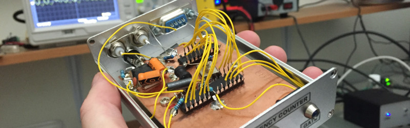
A good example comes via a project from [Scott, AJ4VD], a very simple frequency counter that uses a single 74 series chip at its business end, and counts to over 100MHz. The chip in question is a 74LV8154 dual 16-bit counter which he is using as a prescaler to deliver a rate more acceptable to an ATMega328 microcontroller that does the counting. As he points out, the accuracy of a frequency counter is only as good as its gate timing, and he ensures as accurate a seconds-worth of pulses as he can with a 1PPS signal derived from an inexpensive GPS receiver. The 328 makes its counting available to a host computer via a serial port, and can be easily read through a terminal. He’s built it dead-bug style on a piece of unetched PCB, on which the simplicity of the circuit is evident.
There was a time when a project like this one would have required multiple integrated circuits including a probably quite expensive purpose-built prescaler. Cheap glue logic has now advanced to a stage at which it can be done instead at commodity prices, and we like that.
We’ve featured a few 74-series counters before, including this old-school one and this one also using a 74LV8154.


He for sure uses an uncommon bitrate on the serial interface. 119200 bps ;-)
Anyhow, it’s interesting to see the incredible speed of today’s 74-logic series compared to back in the 70’s and 80’s…
In the early Seventies a counter that could do 20MHz was the price of a good new car…
That’s not true. Heathkit had a frequency counter out in 1971, and it was somewhere in the hundreds of dollars range. Others rapidly followed. Though the norm at that time was a prescaler that only went up to about 150MHz, it was ECL and needed a heatsink. The magazine followed with endless frequency counters, and over the next few years the 15 or 20 MHz upper limit for the basic counter slowly moved up as new families of TTL came along.
In 1974 I spent about $30 at the Rochester hamfest for the TTL and LED readouts to make four digit frequency counter.
And around 1976 Intersil came out with a CMOS IC that was a frequency counter. Other LSI frequency counter ICs followed.
Michael
Well I was thinking of the HP 5244 we had where I first worked, that cost, as I recall being told, over two grand in 1970.
No doubt your HP was a better made, more professional product than the Heathkit. Really though, you can always pay more for a tool that does the same thing. It’s the least expensive tool which is widely available and at least good enough to do the job that determines what is available in a given price range not the fancier more expensive tool that a particular well funded workplace has in it’s shop.
When I was in high school, I used to work as a tech for OPTOELECTRONICS (located on South Florida) back in the late 70’s and early 80’s. Their OPTO-8000 and OPTO-7010 frequency counters went to 600 MHz and used the Intersil ICL7216 with the ECL prescalers made my PLESSEY. No heatsink was needed but they were hand-picked by individual performance testing as were the FET input transistors. I still have my OPTO-8000 and OPTO-7010 units on the bench with me here. They even had a “Low Frequency Multiplier” unit that used a 4046 PLL. Now that was interesting!
Sadly, one day, my girlfriend at the time (I as 16 yrs of age), thought she was pregnant and I was lured into falsely confiding in the boss’s wife when she saw I was emotionally distraught at work that day. A day later, I was told by the boss, “stay away from my (12 yr old) daughter”. Like I was going to impregnate her by being within 20 feet of her … weird. 6 months later, I was “let go”. I liked working there and liked most of the people at that time, especially the two head engineers. BTW: that same daughter (and her husband) now own the company, which moved to Boca Raton. I have looked at their products since then, still making frequency counters but now up in the GHz range. Life was interesting for me during those years. LOL Thank you for the reference to the INTERSIL frequency counter IC, it brings back some memories.
Peace and blessings,
Johnny Quest (and Bandit)
I used to work for OPTOELECTRONICS back in the late 70’s. Their frequency counters at the time were based on the INTERSIL ICL7216 and a PLESSEY pre-scaler front-end (SP8680A or FAIRCHILD 11C90). They could reach 600 MHz without any problem. Before I moved on, they were working on a 1.2GHz Frequency Counter.
The 74 (AC) XX series devices can operate well up to 300 MHz.
I doubt it. 74AC parts are on old slow process, standard voltage, low drive. Even LVC (or other low voltage families) on a more modern process aren’t hitting those frequency.
The 74AC won’t be able to drive a load at 300MHz. Hard to have a full swing into a load if you can’t put out enough current (low drive). The higher I/O voltage means that it also takes longer rise/fall time to reach it (vs something with a 1.8V swing).
But if you prescale by 256, you either lose resolution, or you need to increase the gate time, which slows down operation.
Maybe not much is available now, but there was a time when you could get up to 100MHz with some subset of TTL, so you’d just put a latch and decoder after even the first counter. I like the idea of 74xx390 dual decade counters feeding 8bit latches intended for computer buses, pick right and you get tri-state output for multiplexing. So you can add decoders, or feed a computer’s parallel port in sequence, using the computer as the readout.
Dig around in tv sets or cable boxes, and you can scrounge a prescaler that would give higher frequency use. Though those prescale by some binary number, not a neat ten that makes it easy to use with an existing frequency counter. But it give much better response than 100MHz. Modifying the time base gives direct redout.
Michael
There is a trick to recover the missing bits from the prescaler and use that as part of the counter, so the resolution is still there. Instead of using a simple AND gate as the clock gate, you could use a MUX on the clock input – one side for the input signal, the other side to a GPIO. After the clock is deasserted, count the number of pulses that cause the prescaler output to advance (i.e. when the timer in the uC increment). For a 8-bit counter 256 – # of pulse gives you what was in the prescaler. If you have much longer chain, divide it up again with a MUX so that the counting can be faster.
There was an app note some time ago (Microchip, I think), the trick was that after the gate stopped, they connected the input to a GPIO pin and toggled in more pulses until the output of the prescaler changed. By counting the pulses, you could calculate the state of the prescaler at gate shut-off and recover that lost bit of resolution.
A neat trick.
Hey! micheal can you help me to build upto 100MHz frequency counter using ICs.
This is a really cool build – especially at the price. But he is running the device way, way out of spec (at least per the datasheet). And he isn’t retiming the PPS to the input clock, so timing is not (always) met on the device. This is probably plenty good for the home workbench because a glitchy output here and there can be ignored.
way way out of spec? The clock lines have a min pulse duration of 10ns which is 100MHz
That isn’t the max frequency. That is the smallest (specified) detectable positive, negative, or clock pulse, which if it were 50% duty cycle and insignificant rise/fall time, is 50 MHz. In the datasheet, they have a diagram which shows all of this. Obviously, the part can exceed the specs, but who knows how well.
The spec sheet says 40 MHz is the max frequency (and the specified switching specs line up with that). So, he’s running at 2.5x spec at 100 MHz. I’m sure it does what he says. I just wouldn’t expect such a design to work well if I built it.
You can feed the pps signal to a divide by 2 F/F to get a 50% duty cycle for 2 seconds period. The high (or the low) is going to be 1 second each and use that to gate the counting. No need for fancy retiming etc.
How does that make RCLK meet the timing spec for sampling the internal counter (which is specified as a timing constraint of RCLK with respect to CLKA/CLKB)? I think you are maybe considering the pulse width of the PPS? That isn’t the problem (well, it may be *a* problem).
If the GPS is non-correlated to the frequency you are measuring (ie: pretty much always), the GPS PPS could be any phase w.r.t. CLKA, including well within the hold requirement. In fact at 100 MHz, he is pretty much always violating the specified hold requirement because he is sending a 5 ns positive pulse when the hold time is 10ns, regardless as to the PPS source.
So I’d expect that every once in a while, the output register gets bits in transition.
There are other strategies to deal with this, but resynchronizing PPS to CLKA would be the most straightforward.
Argh… setup requirement, not hold requirement. One day there will be an edit button.
(Didnn’t bother RTFA because I designed/built a CPLD based frequency counter, so a waste of my time to look at a worse design. not sure the clka, clkr etc)
Actually you can’t retime the pps to incoming pulse either if you want to synchronize things. The PPS is used to gate external signal. The only thing that is guaranteed to be running is PPS. At best you can do is to gate the timing.
So I can see these time domains:
PPS: a divide by 2 to get the 1 sec High interval t
External signal: prescaler counter
uC Clock: Timer external clock is synchronized to uC clock. Clock domain crossing & synchronized here. This is why there are limitations on the clock frequency for this part.
In contrast PIC16C54 (microchip app note freq counter) is async and can run at 60+MHz.
I agree that there are more complete ways to do this if you start over. But if you want to discuss the design he has, it has a clock crossing. Unless you are going to redesign the whole thing, you need to either accept that
1. the output is garbled with an unmeasured rate of occurrence (probably infrequent, but more likely the faster the input)
2. or that you have to come up with a scheme to make sure PPS doesn’t happen during the time that the counter is changing. If you really go down this road, you are playing chase the metastability.
I think that for anyone wanting to build a frequency counter at home, that living with #1 is fine. But if you need that frequency counter to always work, you have to be more thorough.
If your pps is synchronized to a uC clock domain, you are throwing the accuracy as the synchronization to the uC clock period can introduce uncertainty in the actual gating timing. The uC clock is in the order of magnitude of 10MHz and may not be accurate and you are trying to measure signal at 100MHz. See the problem?
(The proper modern day synchronous design would need a much faster clock that is a few hundred MHz and synchronize everything to that clock.) The alternative is to gate the incoming sign asynchronously with combinational logic and run the prescalar at the incoming signal clock domain. Yes, the either side of that gating can violate timings, so worse case you have 2 glitches hat might violate timing at the prescaler. Hopefully the parts are harden for metastability.
(That’s why I like CPLD for these things as they are characterized for that and the parts have much faster timing specs.)
Another trick you could try is to take one of the off-the-shelf synthesizer chips (without VCO) available on the market and utilize it’s N counter to divide the input down to something a µC can hack, then use some of the control bits to route said divided signal out to a pin which goes to either an µC or an external counter.
I’ve seen it in an Elektor magazine some years ago, they used an FPGA, but I believe it would be workable with an appropriate µC too.
74hc4040 or some flip-flops achieve that task too.
Here is another that relies on the sample rate accuracy of the sound card of a pc. Although it does have a calibration option. No programming required. Only a 74 hc 4060.
http://opend.co.za/hardware/freqmeter1/index.htm
I quibble the implications of the phrase “These chips have become as ubiquitous as a general-purpose op-amp, or even as passive components” since the introduction of the first of the 74 series in 1964 was concurrent with the first generally useful op amps…. I would say “shares ubiquity with op amps” if you’re going to compare them at all.
Interesting. Manufacturer says 25 MHz is max? http://www.digikey.ca/product-detail/en/texas-instruments/SN74LV8154N/296-34067-5-ND/1594917
The next step in this project for [Scott, AJ4VD] could be to use the atmega328 to also drive a 2 line LCD that could be built into the top of the existing case to display the frequency output so that a serial connected computer wasn’t necessary. I’d love to see that as an upgrade.
Love the dead-bug style prototyping technique. If carefully layed out,
Builds can operate into the GHz range. Also, the edge connectors
off ISA cards serve convenient stand off islands for DIP devices :)
Nice project.. but take it to a gigahertz with the addition of an MC12080 prescaler (currently ~$2 on ebay) Maybe a grounded base transistor input. My personal favorite counter IC is still the ICM7226BIPL. (But on the bench I use one of my old HP counters.)
Good chip.