Let’s say you want to build a Nixie clock. You could go out and find some tubes, source a good power supply design, start whipping up a PCB, and working on a custom enclosure. Or, you could skip all that, and just follow [Simon]’s example instead.
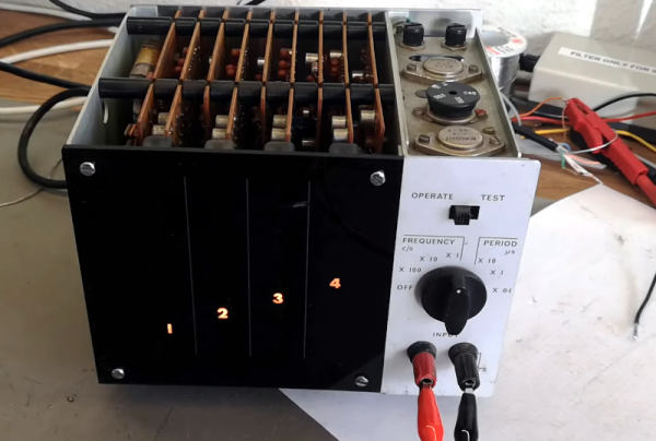
The trick to building a Nixie clock fast is quite simple — just get yourself a frequency counter that uses Nixie tubes for the display. [Simon] sourced a great example from American Machine and Foundry, also known as AMF, the company most commonly associated with America’s love of bowling.
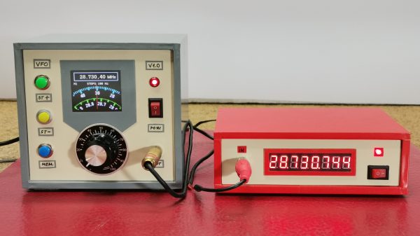
The frequency counter does one thing, it counts the number of pulses in a second. Thus, if you squirt the right number of pulses to represent the time — say, 173118 pulses to represent 5:31 PM and 18 seconds — the frequency counter effectively becomes a clock. To achieve this, [Simon] just hooked an ESP32 up to the frequency counter and programmed it to get the current time from an NTP time server. It then spits out a certain number of pulses every second corresponding to the current time. The frequency counter displays the count… and there you have your Nixie clock!
It’s quick, dirty, and effective, and a sweet entry to our 2025 One Hertz Challenge. We’ve had some other great entries, too, like this nifty hexadecimal Unix clock, and even some non-horological projects, too!
Continue reading “2025 One Hertz Challenge: The Easy Way To Make A Nixie Tube Clock”