3D printers are an exercise in compromise. Generally, you don’t want a lot of mass on your tool head, as that can lead to ringing and other mechanical artifacts on your print. However, direct drive extruders are better for many filaments, and the decision on what printer to build ultimately comes down to a choice between speed, build area, and the ability to print in exotic filaments.
Even in slicing a 3D model, a 3D printing enthusiast must balance the quality of a print versus how long the print will take to squirt out of a nozzle. Now, just about any printer can produce fantastic models at a very high layer height, but no one wants to wait several days for the print to finish.
This balance between print time and print quality has, for the last few years, been completely ignored. One of the best solutions to this we’ve seen is variable layer height slicing. Basically, if you’re printing something without much detail, you don’t need small layers in your 3D print. Think of it as printing the neck of a bust at 0.3mm layer height, and the face at 0.1mm.
Yes, there were a few papers from a decade ago laying the conceptual foundations of variable layer height slicing. 3D printers weren’t exactly common back then, though. Recently, Autodesk’s Integrated Additive Manufacturing Team released Varislice for automatic generation of variable layer heights on a 3D printed object. So far, though, there’s no good automated solution for variable layer height slicing, and the tools for manual configuration of variable layer height slicing are terrible.
For the past few months, Prusa Research has been working on their own edition of Slic3r that includes an easy to use interface for variable layer height slicing. This version of Slic3r was just released, and now it’s time for the hands-on. Does variable layer height slicing work?
To be fair to Slic3r, variable layer slicing has been around for a while. The settings for variable layer height are right there, easily accessible from the plater. It’s not an intuitive interface, though. Setting variable layer heights in the old versions of Slic3r are as simplistic as setting a Z axis offset and the layer height for those layers. The results are the same, but tweaking a model isn’t as easy as the Prusa edition of Slic3r.


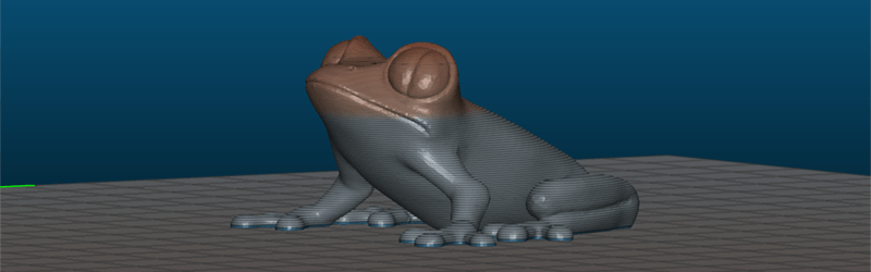
For this example, I’m going to use a model of my own design: the ultimate low-polygon Pokemon. This is my response to 2015’s spasm of low-poly Pokemon, and it’s actually made out of computer code. If you want a great example of how to code polyhedrons in OpenSCAD, here you go.
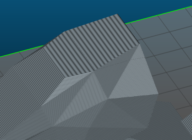
My Porygon model is pretty good, however, the model does have one shortcoming: the top plane of the head is ever so slightly inclined. If that plane were flat relative to the bottom of the model, this wouldn’t be a problem. The slight tilt of the head means there will be obvious visible layer lines right at the most visually appealing part of the model. The solution to this is to either print the model at a very low layer height (which would take a while to print), or to use variable layer height settings on just the top part of Porygon’s head.
Digging Into Slic3r’s Variable Layer Thickness
The UI for the Prusa edition of Slic3r isn’t very different from the standard version. Really, the only change is a ‘Layer Editing’ button at the top of the screen, and a bizarre grayscale layer selection tool on the right hand side of the plater window.
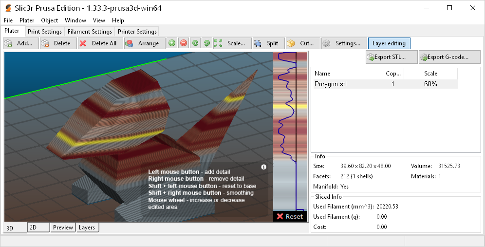
Using the Layer Editing tool, you can easily add detail to portions of a model simply by holding your left mouse button. There’s smoothing, and everything is color coded and easy to visualize. The process is automatic, and Slic3r does all the work for you.
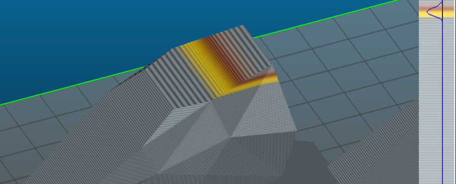
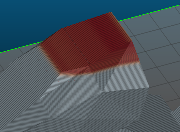
With just a few clicks of the mouse, I’ve corrected the biggest problem with my Porygon model. I now have a very very low layer height where I want it, and I also have a model that will print in hours, not days.
Generating Gcode is one thing, but real results are never displayed on a computer screen. To truly test this out, I need to print these little Porygons out. The results were encouraging:

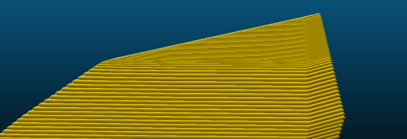
These Porygon were printed with a layer height that was actually too high (0.35mm on a 0.4mm nozzle), but for an example I think it works. The left Porygon clearly shows a ‘stairstep’ feature on the top of its head. This is just how the model was built – the only way to fix this is by printing this model at a lower layer height.
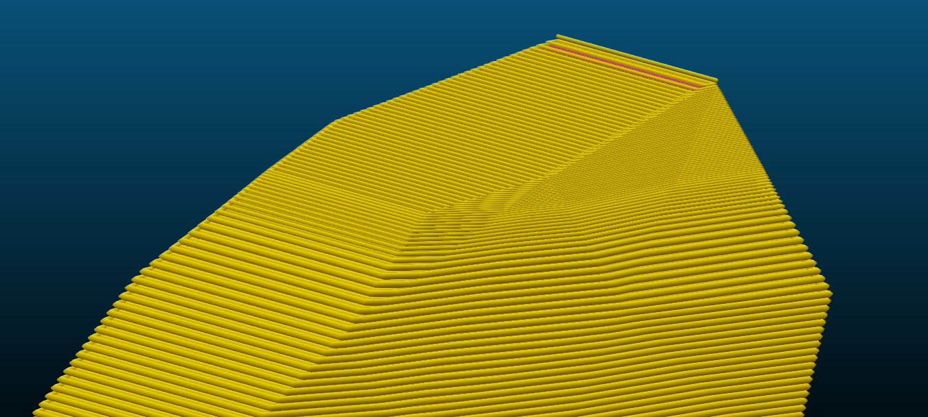
The right Porygon has no discernible stairstep feature on its head. The top of the variable layer thickness Porygon is completely smooth. I could have tuned the thickness of the top and bottom layers for a better print, but this is a very good example of what variable layer thickness printing gets you.
Here’s where things get interesting. At a layer height of 0.35mm, this model takes just over two hours to print. At a layer height of 0.1mm, this model takes five hours to print. The version of this model sliced with variable layer height took just about two hours and fifteen minutes to print. If I were only concerned about the quality of the top plane of Porygon’s head, I get the print quality of a five-hour print in less than half the time.
The Takeaway of Variable Layer Height Slicing
Earlier examples of variable layer height slicing were automatic, meaning the slicer determines where to put detail. Prusa found that the algorithms that determine where to put detail default to the entire print being high detail, and makes automatic layer height useless.
Back in 2013, the main branch of Slic3r received a pull request for adaptive slicing, but it took an exceptionally long time for this to get rolled into the main branch, and again there’s the problem of automatic smoothing resulting in complete smoothing.
For now, at least, manual layer height adjustment is the best we have, and it works very well. This is one of the more interesting advances in 3D printing software recently, and you should check it out.
Now that we have manual variable layer height adjustments, I should mention that the idea of variable detail adjustments is something that has been considered before. This is like variable layer height adjustment, only with selective detail on the x and y axis. Think of a bust, where the face is printed at 0.1mm, and the back of the head is printed at 0.2mm. This idea exists, but there is no implementation. I’ve been hearing about it since 2011 or thereabouts, but so far no one has cracked this algorithmic nut. If you’re looking for a challenge or a master’s thesis, there you go.


Forget variable layer height (or at least slice & print a model that demonstrates the benefits better).
Check out #VelocityPainting! https://plus.google.com/u/0/s/%23VelocityPainting/top
By changing the speed at which the head moves, Mark Wheadon has discovered he can “paint” a grey scale image onto the surface of nearly any print. He has made his code available for others to play with: https://github.com/MarkWheadon/velocity-painting
That’s awesome, especially with the transparent filament… I’m going to have to play with the speeds on my transparent pla.
That’s really interesting! Thanks for sharing!
Good share, and I don’t even have a 3D printer but it’s still somehow an exciting development.
and there goes my weekend.
thank you for the share.
I don’t see it like a fad where one replaces the other. That’s like saying forget screwdrivers, wrenches are the next big thing.
That’s exactly what i was thinking when i wrote the comment..
I often switch between a 0.3mm nozzle and 0.5mm nozzle for similar speed/detail reasons.
How about Variable layer height and dual nozzles of different sizes ?
I wonder how difficult a mechanically actuated variable-sized nozzle would be? Or maybe a rotating thing of different sized nozzles that slot into place?
The problem is making sure the material won’t ooze out from between the nozzle and the part where the nozzle is attached and it only comes out of one of the nozzles holes.
The other problem is that it adds weight, but if you have the actuator at some edge of the build area and drive the head there for each nozzle adjustment (kind of like tool change area, but you just rotate the nozzle there), it does not add much weight.
It’s much easier to simply use a dual extruder and load the same type of filament into both. Dual extruders are commonplace, cheap, and well-supported.
There’s even a “single material dual nozzle” head that uses a valve mechanism to direct the molten plastic to one nozzle or the other. I don’t want to think about cleaning a clog in that thing, however!
I’m amazed that these simple things are happening so slowly.
Prusa has done some great things w/ their version of Slic3r, fixing a lot of the nagging issues along the way. Slic3r is still not the only tool in my toolbox, but I do use it a lot more now than before Prusa’s fork existed. Great work!
It’s sad they had to fork instead of cooperate on a single codebase
welcome to the wonderful world of git, where persona of the developer is more important than the software he is contributing to. Github even encourages you to fork something!
It is, yes, but i think Prusa should rename their fork to avoid confusion. Prusa edition does not quite cut it.
I see what you did there…
I did not know there was ongoing development on Slic3r. I thought it stopped at 1.2.9.
Are there other forks?
“Think of a bust, where the face is printed at 0.1mm, and the back of the head is printed at 0.2mm. This idea exists, but there is no implementation.”
You mean this? http://slic3r.org/blog/modifier-meshes
It’s not automatic, but it’s exactly analogous to the layer height thing.
Wasn’t there an article, or maybe it was just a comment on a related article, here some time ago about this?
I’m waiting for fine outer shells, with strong, quick and thick infills. Coupled with this idea of adaptive layer height. And finally with the ability to build up a base and make a curved top layer. Making shallow gradients with a single top layer at an angle.
The Robox printer from CEL with it’s dual nozzle system would actually be perfect for this, the first generation printer had two nozzles on one head, one with a fine hole, the other with a big hole, fed by one spool of filament. I’m not shure how well the slicer software they have works right now, but the hardware they have would be perfect for this.
Your other option would have been to put Porygon up on its “heels” with some cutaway support material to make that incline horizontal. Of course, that makes the beak a shallow incline, but there’s probably an art to balancing those things out to minimize stairstepping and excess support material.
Great article. For the specific example of the Porygon, could you not have also rotated the model slightly so the top of the head was level with the print bed and a small raft/support would be added below the feet? It would make the bottom of the feet ugly, but that seems to fit the design goals. I appreciate that this was just an example to demonstrate variable layer slicing, and for that it looks like a fun project!
For this specific example you could get really nice results by splitting it down the middle and printing in two halves, then gluing the flat sides together. If you get the first layer right and align carefully it’s incredibly hard to spot the join.
Not always possible though.
Or have a simple shape like a rectangle with an embossed logo/graphic repeated up the side. Thick layers will pixelate image, fine layers will reveal it.
Thanks for the tip!
For these kind of things a 6 axis 3d printer would be ideal. It’s like a dual kossel 3D printer where the build plate sits on the second motor controlled arm. I’ve no idea how to sluce the object for that but I’ve seen a video of it working.
Brian, don’t you mean a very low layer height?
PORYGON! I clicked on the article out of interest on the topic. Saw porygon, staid :)
“very high layer height” should be “very low layer height” or “very high layer resolution”
Slicing seems like the next big frontier, actually. A few dream items:
– Smart varying of layer height
– printing infill and support with intellegent layer height .. they generally only need to be precise when getting near a boundary
– structured infill that minimzes infill when it’s far from a boundary (I know thst some version of this exists)
– most importantly .. smart machine compensation. We do a lot of model tweaking to compensate for machine characteristics. Unfortunately, thst diminishes the value of the model. Something that could solve the inverse problem, and generate a machine specific, corrected gcode that takes an ideal model as input and yields a nearly ideal result would be awesome. Stuff like enlarging holes a bit and that sort of thing. .. small holes are almost always way too small (and the inaccuracy depends on orientation).
I think there was an article on this in HaD a while back, but I’d like to see direct support for engineering formats, eg Step, and the ability to highlight surfaces that need to be made more accurate, or heavy duty.
There is already the ability to print infill with thicker layers than perimeters, at the same Z position. Why not adapt that so that you can print different parts of the perimeter at the same Z position with different layer thickness? Then you could print the shallow-angle portion of the Porygon’s head with fine layers and the back of its head (where it’s steeper) with thicker layers.