When you leaf through a basic electronics textbook, you’ll find chapters describing in detail the operation of the various components. Resistors, capacitors, inductors, and semiconductors. The latter chapter will talk about P and N type regions, introduce us to the diode, and then deal with the transistor: its basic operation, how to bias it, and the like.
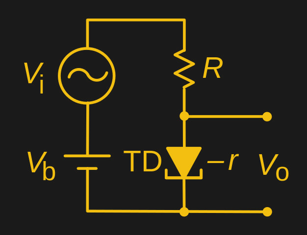
We’re all used to conventional resistors, devices that follow Ohm’s Law. When you apply a voltage to a resistor, a current flows through it, and when the voltage is increased, so does the current. Thus if you use a positive resistance device, say a normal resistor, in both the top and the bottom halves of a potential divider, varying the voltage fed into the top of the divider results in the resistor behaving as you’d expect, and the voltage across it increases.
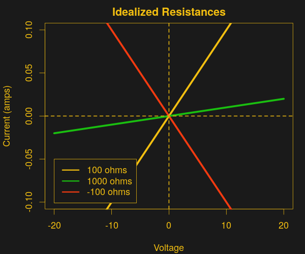 In a negative resistance device the opposite is the case: increasing the voltage across it results in decreasing current flowing through it. When a large enough negative resistance device is used in the lower half of a resistive divider, it reduces the overall current flowing through the divider when the input voltage increases. With less current flowing across the top resistor, more voltage is present at the output. This makes the negative resistor divider into an amplifier.
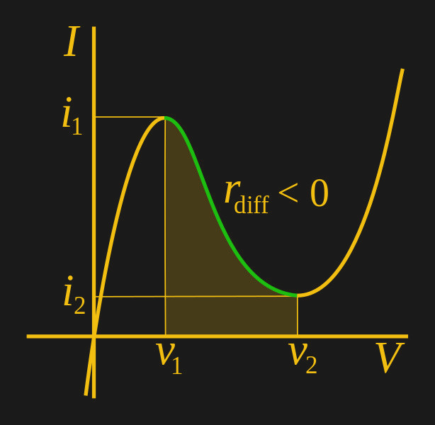
The tunnel diodes we mentioned above are probably the best known devices that exhibit negative resistance, and there was a time in the early 1960s before transistors gained extra performance that they seemed to represent the future in electronics. But they aren’t the only devices with a negative resistance curve, indeed aside from other semiconductors such as Gunn diodes you can find negative resistance in some surprising places. Electrical arcs, for example, or fluorescent lighting tubes.
It’s unlikely that you will encounter a tunnel diode or other similar electronic component outside the realm of very specialist surplus parts suppliers. We’ve featured them only rarely, and then they are usually surplus devices from the 1960s. But understanding something of how they operate in a circuit should be part of the general knowledge of anyone with an interest in electronics, and is thus worth taking a moment to look at.
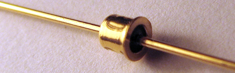
1N3716 tunnel diode header image: Caliston [Public domain].


No, this is not a negative resistance. A really negative resistance does not exist. I do not know the right english term. The tunneldiode is working in the negative differential resistance region (translated by leo dict). This also exists in gas discharge lamps (neon).
Negative small-signal resistance. Or if you said negative differential resistance then people would understand you too.
In practice I think “negative resistance” would also be well-understood because the listener will know that energy is still be conserved, so you must be talking about the gradient.
the correct term is negative dynamic resistance, now in this form makes a lot more sense :)
>What is a negative impedance converter
Yeah, my post was a reply to the accusation that no device can have true negative resistance, as it would have to inject energy into the circuit. A negative impedance converter does just that and my phrasing of “>What is a negative impedance converter” was not actually a question, but rather a statement: “the aforementioned accusation is false, here is a counterexample”.
Back in the 70s, most of the electronic books in the Oxford City Library mentioned tunnel diodes as a means to build FM transmitters. Even back then I knew I’d never find one in the scrap TVs I used to desolder for parts.
Actually, GE TV sets in the USA used tunnel diodes in their UHF tuners as their local oscillators. I have a couple tunnel diodes in my junk box scavenged from old tuners.
The attractive thing about tunnel diodes was that they could amplify and oscillate and switch at frequencies far higher than the best transistors at the time. Operation at 1 GHz was possible when normal transistors couldn’t even reach 100 MHz.
Quote [Matt Brunton]: “Back in the 70s”
TV’s were VHF only in the 70’s. So there were no tunnel diodes in the UHF tuner that the TV didn’t have.
:o)
May depend on what country you’re in, but US televisions had UHF at least since 1976. I know, because I got to take our old one apart when it finally croaked. Hybrid device – it was solid state until it hit the Big Honking Sweep Tubes. JCPenny Brand. :-) Also, Dr. Who was on Channel 26 at 11:00pm.
You’re kidding- thought I was the only soul who remembered Dr Who in the Tom Baker years…
OBEY THE SCARF! OBEY! OBEY! OBEY!
I lived in Peoria ILL. we only had uhf at grandma’s house only. When My grandmother moved from Chicago they had vhf only tv , she had to get a converter box, That was between 1971 till 79…
We never had cable so we are talking Lawrence Welk and he haw here…
later
Here in Canada we had UHF TV stations in the mid 70s, the UK in the 60s, and the first UHF TV station in the USA went on the air in 1949..
Maybe in your shitty country. My christmas present in1967 was a b&w 19 in TV with VHF and UHF.
There’s a good history of UHF TV in the USA at . There were something like 16 stations broadcasting UHF by 1953.
1950’s TVs were VHF-only, so a little UHF converter box was used that converted UHF to VHF channel 2 or 3. Sometime in the 1960’s the FCC required TV manufacturers to include UHF.
As a kid in southwestern Michigan in 1960, we got the “Big 3” TV networks (ABC, NBC, and CBS) on UHF channels 16, 22, and 28 out of South Bend and Elkhart IN. The VHF stations in Detroit and Chicago were too far away to watch reliably.
And, I still have that tunnel diode out of a UHF TV tuner that RÖB thought didn’t exist. :-)
Hackaday seems to have deleted the url. It’s uhftelevision.com with the usual http www stuff in front of it.
I used to own a 1957 Philco with built-in VHF and UHF tuners.
UHF TV in the US existed well before the 70s. I don’t know when UHF broadcasts in the US started, but In 1961 congress enacted a law (“The All-Channel Receiver Act”) that allowed the FCC to require that all television set manufacturers must include UHF tuners along with VHF tuners in the same console in 1962.
You can get the same effect with two FETs, as in the Lambda diode. The wrench in the works is one is a P-channel FET, which, not a rare as Tunnel Diodes, are still rare enough.
It can also be at time accomplished with a plain old 2N2222: see http://www.keelynet.com/zpe/negistor.htm (it is basically a scan of an 1975 issue of Popular Electronics that I sent to Marcelo, who then forwarded to Keelynet)
If you’re interested and having trouble finding a P-channel FET, you can replace it with a PNP transistor. Check out the circuit at http://www.zen22142.zen.co.uk/Theory/neg_resistance/negres.htm (or the slightly modified circuit I described at https://ceworkbench.wordpress.com/2013/03/31/playing-with-negative-resistance/).
I checked out your link and appreciate the info.! I might just go ahead and breadboard the audio oscillator and check it out. Thanks!
“most of the electronic books in the Oxford City Library ”
Ah, so you were the other person pulling out all those books :) 1980s for me, but yes.
Probably me, yes. And if the book didn’t contain circuits with tunnel diodes, they were almost guaranteed to be full of valve designs or some odd op-amp in a round can.
I remember being pleased when I could finally browse the adult collection where there were at least some RSGB-related books.
So, the little neon lamps should also have a negative restance. Has anyone used them as amplifiers?
They prototyped ENIAC’s logic circuits using neon lamps because they were way cheaper and reliable than tubes but much slower.
I would love to see a circuit for this (neon bulb audio amp) — for the record, I asked Creepy Uncle Google and didn’t get a useful answer…
Most of the neon lamp experimentation happened BG (Before Google), so much of it is not on the web. I remember an entire book on neon lamp circuits from the 1960’s (Howard W. Sams, if memory serves) that did have some audio amps with neon bulbs. More of a novelty than a useful circuit.
There are even audio amplifiers that use only standard diodes! The trick is to use the diode’s reverse recovery time. You “pump” it with a high frequency oscillator, and add the audio signal to it. The audio modulates the reverse recovery current, causing a power gain.
Pictures, dammit! (said with grin, not grimace)
I’m a visual person. It’s a hundred times harder for me to make something without a diagram of some sort…
Here one is used for an oscillator. http://www.rfcafe.com/references/qst/neon-bulbs-qst-july-1953.htm That’s just an amplifier with more feedback right?
Kinda sorta – may be difficult to keep it biased in its negative restance region to serve as an amplifier…
negative resistance != negative differential resistance, i.e., R != -r.
a tunnel diode always has a positive resistance, and also a negative differential resistance in some operating areas.
it never exhibits a negative resistance.
Technically it’s a negative resistance-voltage coefficient.
“It’s unlikely that you will encounter a tunnel diode or other similar electronic component outside the realm of very specialist surplus parts suppliers.”
Well, you can still buy them easily inside tunnel diode-based power detectors.
Well, actually you would be surprised how widespread tunnel junctions actually are. However, they are nowadays not used for their negative differential resistance region, but for making a serial connection in epitaxial semiconductor stacks. Quite common in space solar cells, diode lasers and high power LEDs.
Or make your own, using a surplus infrared LED gently “cooked” with overcurrent.
This works, not as well but it oscillates in much the same way as a reverse biased E-C transistor.
Want to experiment with a tunnel diode-like device using only parts you already have?
Some transistors (2N2222, but also other NPN too) exhibit a negative differential resistance region if the base is left floating and are reverse polarized.
Since it is more an unintended effect, not all of them do. Probably depends on the process used to manufacture them. You also need to bias them at ~10V as opposed to the few hundred millivolt of a real tunnel diode.
Source: https://www.youtube.com/watch?v=rpGOKGrcpAk
I ended up missing you comment, but attached a link to an article on negistors. Back in the 80’s I built a little box to sort transistors for this effect, but really didn’t otherwise do much (between work, college and getting a woman pregnant, my 80’s dance card was full).
Thanks for the link, I’m reading the Popular Electronics article right now
Many analogue Tektronix oscilloscopes have trigger circuits that are based on tunnel diodes. They are also used to generate fast risetime signals in, for example, time domain reflectometers.
Yep, and they’re fragile as heck and getting tougher to find! They’re also used in the sampling gate on Tek’s analog sampling scopes. Truly some amazing technology for it’s day.
Are we talking the low-end ‘scopes with the blue-moulded exteriors and the truely hard-as-heck to find shells?
*yawn* Not a hack, and a rehash of an old article (http://hackaday.com/2016/03/30/a-ridiculous-way-to-light-an-led-candle-power).
*yawn* you “not-a-hackers” are nothing more than rehashes of each other.
But thanks for the link.
not a not a hack?
Couldn’t you make something that works similarly with a depletion mode mosfet? the voltage across it would turn it into a resistance across a small range, granted you might have to make a clever resistor arrangement to keep it from latching itself on due to start-up state being fully ‘on.’
You can make your own negative resistance devices from zinc oxide: http://www.sparkbangbuzz.com/els/zincosc-el.htm
When reading this article I was surprised that the author didn’t mention this article! I’ve read and enjoyed a lot of the articles at sparkbangbuzz.com.
With an opamp, you can build a ‘negative impedance’ circuit that acts as if it was the negative value of whatever resistor you put across two given terminals. I built this circuit for a project in one of my undergrad classes. It acts basically like it should up to the rails of the opamp. Works for any impedance, including capacitive or inductive loads.
The basic circuit is here: https://en.wikipedia.org/wiki/Negative_impedance_converter#Negative_impedance_circuits
Just a couple matched resistors, an opamp, and the part you want to create a negative version of.
No discussion of negative resistance would be complete without discussion of gas discharge tubes.
https://en.wikipedia.org/wiki/Pearson%E2%80%93Anson_effect
There are still some “negative resistance” devices in common use: DIACs used in (for example) AC Lamp dimmer TRIAC trigger circuits, and SIDACs and SIDACTORs commonly used (and/or legally required) as protection circuits for communications links. All rather optimized for “switching” sorts of applications; I don’t know if you can keep them in their “negative resistance region” enough to be useful as amplifiers. They can make nice HV high-current relaxation oscillators, though (for example, you can convert most old-style Xenon flash attachments to repeating strobes by putting a 150V SIDAC across the trigger inputs.
I’m still recovering from GM and their use of “Negative Current”, which I learned about reading the service bulletins for my power steering…. ” At zero mph, a negative current of approximately two to three amps flows to the Magnasteer coil”
A functional battery is a true negative resistance
This article is somewhat remiss in not mentioning of one of the most versatile negative-resistance devices available to us low-voltage wonks, the unijunction transistor, or UJT (UJTs are no longer manufactured, having been replaced by the more versatile programmable unijunction transistor, or PUT).
Look it up; get some; have fun.
Once upon a time, 1987 the german Elektor Magazin released a Schematic based on this feature of tunnel diodes called “Tunneldioden-Akkulader” (Tunnel diode – battery charger). Basically some of the diodes in series on a heat sink, which was ment to be heated up. Later on, the schematic found it’s way in the book “303 – Schaltungen”, which is exactly the place I found it (at the age of 12) and was really thrilled by the idea. Much much later I discovered the full Story it seemed that the Editor of the “303 – Schaltungen” completely missed the fact that it was the April edition of the magazin.
An RF oscillator – Colpitts circuit or similar – can be analyzed as a resonant circuit connected to negative resistance of the transistor and feedback circuit. Or this is what I vaguely remember from university :D
Phase 1: Connect millions of negative resistance devices for 1.21GW of free energy
Phase 2: ?
Phase 3: Profit