[Eric Schlaepfer] tends to turn up to Maker Faire with projects you simply don’t want to miss. This year is no different. Twelve months ago we delighted in seeing his 6502 processor built from an enormous reel of discrete MOSFETs. At the time it was freshly built and running random code to happily blink the LEDs reflecting activity in the registers. This year he’s given that blinking meaning and is running real programs on his Monster 6502 processor.
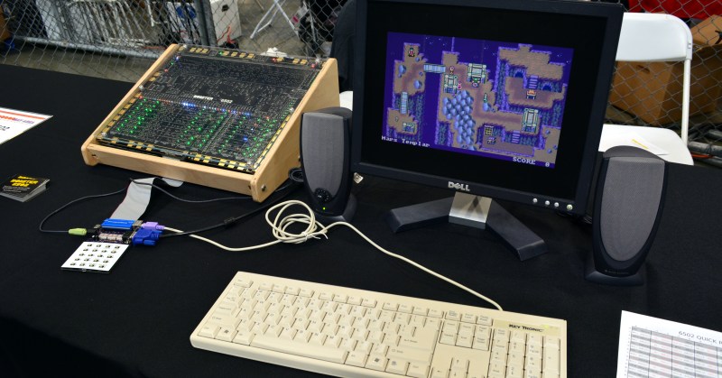
A processor isn’t a computer until the peripherals are built up around it. He’s done that with a new board called the MIM-1 for Monster Interface Module. It includes a keypad for input and six 7-segment displays for immediate output. This gives the user direct control over the processor to peek and poke at registers, set breakpoints, and manage the operation of the processor. It also brings audio connectivity, VGA, and PS/2 keyboard connectivity so that the user can interact with code running on the 6502 using a screen and a keyboard.


There is even a Y-modem protocol built into the MIM-1 that allows you to save and load programs. This is satisfyingly shown off in the video when [Eric] loads up a game he wrote himself. The audio and video hit your right away — it turns out that [Eric’s] brother is a pixel artist and was happy to jump in and help out with the project. But don’t be fooled by the cheap trick of running a game… the real mastery her is first in the Monster 6502 itself, and second in the MIM-1 board which emulates all of the computer peripherals around it by using an STM32. This is truly spectacular work.
Keep your eye on the Monster 6502 page as we suspect [Eric] will document the MIM-1 once the excitement of BAMF is past.


“Twelve months ago we delighted in seeing his 6502 processor built from an enormous reel of discrete MOSFETs.”
That’s some old skool stuff right there. Just one level above building one’s own FETs.
It’s entirely in the realm of possibility to use chemicals, metal solder paste stencils and a UV light to make a large 6502 out of a full silicon wafer. With minor modification you could even add a bunch of LEDs to indicate values.
But you forgot to mention the need to get the doping chemicals to diffuse dopant into the wafer, not to mention the need for oxide growths. These require equipment… accurate equipment. starting with the lithography, moving to the diffusion/implant, and including oxide growth, steam ox, and dry o2 ox. Yes, it can be done in a LARGE garage… with a LARGE budget… not something in the realm of possibility for most people. It’s simply not enough to dump some chemicals on a wafer, and expect it to be doped. The dopant must be introduced to the Si lattice, then activated. Activation occurs only at ~1000 degrees C. Not to mention that the dopant must first be introduced into the lattice as interstitials, also not easy.
“These require equipment… accurate equipment.”
Not really. If you are making it as large as a silicon wafer then there is a lot of room for error.
Heating also shouldn’t be a problem considering you can cheaply build an electric foundry.
Sure, it might cost you $500 to do your first wafer but then you can make your own mosfets. :)
Addendum. Have you considered the clean room requirements? Also the toxic chems needed during photomask removal and oxide etching? These chems need special attention, meaning more equipment. You can’t sling HF around willy nilly.
You can once…
HF? High Frequency? I do sling it around regularly. If that’s the wrong acronym, then kindly define it.
Hydrofluoric acid / Hydrogen fluoride solution. Dissolves SiO2.
A very dangerous acid.
Yes, what TREZA says: Hydrofluoric acid. Colloquially, if you ever smell HF, it’s too late, you’re done for.
Less hyperbolically, it’s is nasty stuff: https://emergency.cdc.gov/agent/hydrofluoricacid/basics/facts.asp
I wonder how hard it would be to build a discrete transistor version of a 6532 RIOT and an Atari TIA and produce a full discrete transistor version of the Atari 2600 that could run 2600 games?
If you’re aiming for a complete Atari, I wouldn’t bother, as it wouldn’t have worked.
If you would have read the link, you would have seen that this board runs only at 60KHz vs ~1MHz for a real 6502 due to the NMOS capacitance. You cannot drop this board into a real working 6502-based computer and expect it to work as-is, even with an original machine.
A CMOS version should work better…
No, a CMOS version would still be limited by the discrete MOSFETs’ gate capacitance.
The original 6502 used depletion mode MOSFETs and this unit is using enhancement mode MOSFETs and that accounts for *most* of the speed difference. Even if he used depletion mode MOSFETs then it still probably wouldn’t reach the speed of the original chip simply because of it size and the signal path lengths.
Gate capacitance is less of a problem with depletion mode MOSFETs because you *drive* the gate *OFF* and this drains the capacitance.
Sure, the capacitance is still there, but with a CMOS driver, you have a low impedance path to charge it.
The original 6502 used NMOS technology. This consists of enhancement and depletion MOSFETs, but normally the depletion mode FETs are not driven at all in NMOS circuits, they just act as drain resistor (pull up), their gates are shorted to the source. On a silicon chip its easier and more space and power efficient to use the dep. FETs than to make resistors.
It is possible that they used some other special circuits with the dep. FETs, but the speed limit lies in the size and the huge capacitance of the discreet FETs. These are huge and powerful compared with integrated FETs in chips. The FETs of the internal logic are usually much smaller (I estimate good for something like 0,2mA) than the IO FETs and even these are only designed for something like 20mA compared to the discreet which are probably something like 2N7002, good for 200mA.
I really hope they sell kits someday, id love one of these!
Because the kit would be et least $5000,- it’s unlikely. I guess they’ll give you the Gerbers and BOM right now.
Is that Warhammer 40K?
Ugh, HaD, you buried the lede here. What’s the graphics hardware running that game he wrote? No way that a 6502 made of discrete components (with a clock measured in kilohertz) is pushing those pixels at VGA resolution by itself. Did he make a little sprite engine on the MIM board?
Was thinking the same thing, even with the extra hardware doing all the work it’d surely take ages for the system to load the sprites into the vram?
Interested to see some documentation of how it works, at the moment I’m still banging rocks together like a caveman with 80×25 B/W Text only
If you look closely at the MIM quick reference, there is a sprite engine of some sort on there that supports 8×8 and 16×16 sprites, over an 80×25 tiled background.j
There’s mention of a STM32 part… which is probably doing all the pixel pushing.
Quinn, the MIM-1 uses an STM32 to emulate the rest of the computer hardware. The VGA video is being generated by a DMA module and three timers.
That is cool :) Very nice job. I like it like that with the old skool box.
Is the next step to make a discrete SID so it can play music? :D
For some reason I want to see this thing plugged into an Apple II motherboard.
That’s not without challenges. The Apple ][ interleaves video fetches tightly with CPU bus phases, and so is very tightly coupled to the CPU frequency.
You would need an adaptor circuit (a synchronizer circuit, basically) to proxy bus accesses between the 1MHz domain and the variable-speed MOnSter6502 domain, and to provide the necessary timing signals in both directions.
The MOnSter6502 FAQ actually addresses this:
“Can you hook it up inside an Apple ][ and run Oregon Trail?
No, not directly. It’s neat to think of plugging the MOnSter 6502’s [s]in-circuit emulator (ICE)[/s] in-circuit replica (ICR) cable directly into a socket inside an Apple ][, but that wouldn’t actually work. The Apple ][ design relies on a number of clever tricks that derive timing for video generation and peripheral control from the main clock signal — all of which will fail if you need to run at a slower speed.
There are some ways to get around limitations like these. For example, the Replica I computer (an Apple I clone) uses a Parallax Propeller chip to emulate a system clock and some of the timing-dependent external processing.”
If not an in an Apple ][ due to the video timing and so forth, would it work as a CPU replacement for a KIM-1?
Oh, and then there’s the floppy drive as well. It requires exact cycle timing for its loops.
But, presuming you could solve those issues, it’d be pretty cool.
Why are there no articles featuring the 6809/6309?