
If you have ever read advanced textbooks or papers about electronics, you may have been surprised to see the use of complex numbers used in the analysis of AC circuits. A complex number has two parts: a real part and an imaginary part. I’ve often thought that a lot of books and classes just kind of gloss over what this really means. What part of electricity is imaginary? Why do we do this?
The short answer is phase angle: the time delay between a voltage and a current in a circuit. How can an angle be a time? That’s part of what I’ll need to explain.
First, consider a resistor. If you apply a voltage to it, a certain current will flow that you can determine by Ohm’s law. If you know the instantaneous voltage across the resistor, you can derive the current and you can find the power–how much work that electricity will do. That’s fine for DC current through resistors. But components like capacitors and inductors with an AC current don’t obey Ohm’s law. Take a capacitor. Current only flows when the capacitor is charging or discharging, so the current through it relates to the rate of change of the voltage, not the instantaneous voltage level.
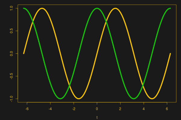 That means that if you plot the sine wave voltage against the current, the peak of the voltage will be where the current is minimal, and the peak current will be where the voltage is at zero. You can see that in this image, where the yellow wave is voltage (V) and the green wave is current (I). See how the green peak is where the yellow curve crosses zero? And the yellow peak is where the green curve crosses zero?
These linked sine and cosine waves might remind you of something — the X and Y coordinates of a point being swept around a circle at a constant rate, and that’s our connection to complex numbers. By the end of the post, you’ll see it isn’t all that complicated and the “imaginary” quantity isn’t imaginary at all.
Simplifying Assumptions
Start with an audio signal of someone speaking and feed that into your circuit. It is awash with different frequencies that change constantly. If you had a circuit with only resistors in it, you could pick a point in time, find all the frequency components present or the instantaneous amplitude, derive the instantaneous currents, and you could use conventional techniques on it. You’d just have to do it over and over and over again. If the circuit involves inductors or capacitors, whose behavior depends on more than just the voltage across them, this becomes very difficult very quickly.
Instead, it is easier to start with a sine wave at a single frequency and assume that a complex signal of many different frequencies is just the sum of many single sines. One way to think of a capacitor is to consider it a resistor that has higher resistance at lower frequencies. An inductor acts like a resistor that gets larger at higher frequencies. Because we are only considering a single frequency, we can convert any capacitance and inductance values to an impedance: a resistance that is only good at the frequency of interest. What’s more is that we can represent impedance as a complex number so that we can track the phase angle of the circuit, which directly relates to a particular time delay between voltage and current.
For a true resistor, the imaginary part is 0. That makes sense because the voltage and current are in phase and therefore there is no time delay at all. For a pure capacitor or inductor, the real part is zero. Real circuits will have combinations and thus will have a combination of real and imaginary parts. Numbers like that are complex numbers and you can write them in several different ways.
Complex Review
The first thing to remember is that the word imaginary is just an arbitrary term. Maybe it is better to forget the normal meaning of the word imaginary. These imaginary quantities are not some kind of magic electricity or resistance. We use imaginary numbers to represent time delays in circuits. That’s all.
 There is a long story about what imaginary numbers mean in pure math and why they are called imaginary. You can look that up if you are a math-head, but you should know that math books use the symbol i for the imaginary part of a complex number. However, since electrical engineers use i for current, we use j instead. You just have to remember when reading math books, you’ll see i and it isn’t a current, and it is the same as j in electrical books.
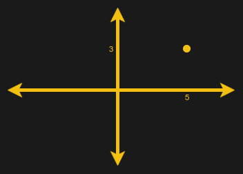
There are several ways to represent a complex number. The simplest way is to write the real part and the imaginary part as being added together along with j. So consider this:
5 + 3j
We say the real part is 5 and the imaginary part is 3. Numbers written in this form are in rectangular format. You can plot it on the number lines like this:
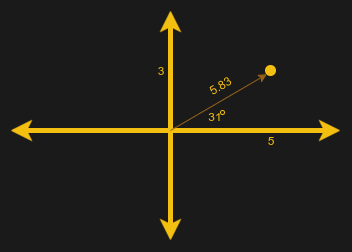 That leads to the second way to write a complex number: polar notation. If the point on the graph is 5 + 3j, you can note that a vector can represent the same point. It will have a length or magnitude and an angle (the angle it makes with the X-axis of the graph). In this case, the magnitude is 5.83 (about) and the angle is just a little under 31 degrees.
This is interesting because it is a vector and there are a lot of good math tools to manipulate vectors. It is going to become really important in a minute because the angle can correspond to a phase angle in a circuit and the magnitude has a direct physical relationship, as well.
Phase Angle
Remember that I said we do an AC analysis at a single frequency? If you plot the AC voltage across and the current going through a resistor at some frequency, the two sine waves will line up exactly. That’s because a resistor doesn’t time delay anything. We’d say the phase angle across the resistor is zero degrees.
However, for a capacitor, the current will appear to rise before the voltage by some amount of time. This makes sense if you think about your intuition about capacitors at DC. When a capacitor is discharged, it has no voltage across it, but it will consume a lot of current — it temporarily looks like a short circuit. As the charge builds, the voltage rises but the current drops, until the capacitor is fully charged. At that point, the voltage is at a maximum, but the current is zero, or nearly so.
Inductors have the opposite arrangement: voltage leads current, so the curves would look the same but the V curve is now the I and the I curve is now the V. You can remember that with the simple mnemonic ELI the ICE man, where E is voltage just like in Ohm’s law. When you talk about phase shift in a circuit, you really mean how much the current leads or lags the voltage at a given frequency. That’s a key idea: phase shift or angle is the amount of time the current leads or lags the voltage. You can also measure phase between other things like two different voltage sources, but generally when you say “this circuit has a phase shift of 22 degrees” you mean the voltage vs the current time delay.
Keep in mind a sine wave is like a circle bent to fit a line. So if the start of the sine wave is at 0 degrees, the top of the positive peak is 90 degrees. The second 0 crossing is 180 degrees, and the negative peak is 270 degrees–just like the points on a circle. Since the sine wave is at a fixed frequency, putting something at a particular degree mark is the same as expressing a time.

In the case of a resistor, the shift is 0 degrees. So in complex notation, a 100 ohm resistor is 100 + 0j. It can also be 100∠0. For a capacitor, the current rises before the voltage by 90 degrees so a capacitor has a phase shift of -90. But what’s the magnitude?
You probably learned that the capacitive reactance is equal to 1/(2πfC) where f is the frequency in Hz. That’s the magnitude of the polar form. Of course, since -90 degrees is straight down the number line, it is also the imaginary part of the rectangular form (and the real part is zero). If capacitive reactance (Xc) is equal to 50, for example, then you could write 0-50j or 50∠-90. Inductors work the same but the reactance (Xl) is 2πfL and the phase angle is 90 degrees. So an inductor with the same reactance would be 0 + 50j or 50∠90.
Finding the Power
Let’s look at a quick example of what these phase angles are good for: calculating power. You know that power is voltage times current. So if a capacitor has 1 V across it (peak) and draws 1 A through it (peak), is the power 1 watt? No, because it doesn’t draw 1 V at 1 A at the same time.
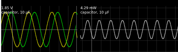
 Consider this simulation (see figure to the right). You can see the traces to the left show the 90 degree phase shift very clearly (the green trace is voltage and the yellow one is current). The peak voltage is 1.85 V and the current peaks at about 4.65 mA. The product of the voltage times the current is 8.6 mW. But that’s not the right answer. The power is actually 4.29 mW (see the graph on the right). In an ideal capacitor, power isn’t consumed. It is stored and released, which is why the power goes negative. Real capacitors, of course, exhibit some loss.
Note that the power supply doesn’t provide 4.29 mW, but much less. That’s because the resistor is the only thing consuming power. The voltage and current are in phase for it and some of the power it dissipates is coming from the capacitor’s stored charge.
Circuits
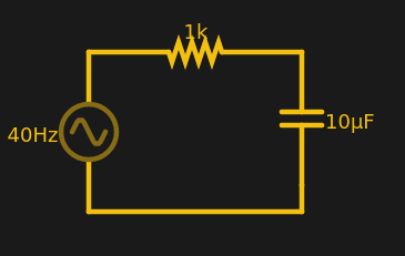
The magnitude of the vector is usable in Ohm’s law. For example, at 40 Hz, the Xc of the example circuit is just under 400 ohms. So the total complex impedance for the RC circuit is 1000 – 400j.
If you are adept with vectors you could do polar by writing 1000∠0 + 400∠-90. However, it is usually easier to write the rectangular version and convert to polar (Wolfram Alpha is good at that; just remember to use i instead of j). The magnitude is just the Pythagorean theorem and the angle is simple trig. I am not going to go into it, but here’s the formula where R and J are the real and imaginary parts, respectively.
mag=SQRT(R^2+J^2)
phase=arctan(J/R)
Our example, then, is 1077∠-21.8.
So what’s the power coming out of the voltage source? Power is E^2/R (or, actually, E^2/Z in this case). So 25/1077 = 23 mW peak. The simulation shows 22.29 and since I rounded a few values, that’s close enough.
That’s It?
That’s not it, of course, but it is all you need to know for a lot of purposes. Many hobby-level electronic texts skimp on the details and just work with magnitudes. For simple circuits, this can work, but for something complex (no pun intended), it gets hairy fast.
By the way, this example showed to elements in series. However, you can add reactances in parallel just like you do resistors in parallel.
The key concepts you need to remember are:
- The analysis of an AC circuit mostly occurs at a single frequency with a sine wave input.
- Imaginary numbers aren’t imaginary.
- Magnitudes of complex numbers in polar forms can be treated like a resistance.
- Phase angle is the time delay between the voltage and the current waveform.
There are a lot of details I glossed over. You probably don’t need to know how i is really the square root of negative one. Or how Euler’s number plays into this and the simplicity of integrating and differentiating sine waves written with an amplitude and a phase angle. If you are interested in math history, imaginary numbers have quite a story behind them. If you want something more practical, Khan Academy has some useful videos. However, what’s covered here should be all you need to know to work with AC circuits.


“If you have ever read advanced textbooks or papers about electronics, you may have been surprised to see the use of complex numbers used in the analysis of AC circuits.”
I suppose. Once I got into AC, which wasn’t long from DC, imaginary was introduced rather quickly. And that was within the same textbook. And that’s not even getting into math class.
The description of a term as “imaginary” has been a stumbling black since it was first used. I think it would be great if all fields adopted I and Q.
“That means that if you plot the sine wave voltage against the current, the peak of the voltage will be where the current is minimal, and the peak current will be where the voltage is at zero.” This is true for sin and cos but it might be better to generalize: ‘That means that if you plot the sine wave voltage against the current, the peak of the voltage will be where the current is changing the fastest, and the peak current will be where the voltage is changing the fastest.’ This then relates to the previous part about rate of change of voltage versus current in a capacitor.
Well that made about as much sense as a chocolate teapot. :)
Its all about how fast it is changing instead of how much you got. There is so much to say about complex numbers and science that you have to stop somewhere. I would add a little something about the reason for it all being that some things just behave that way. Regular multiplication doesn’t work, but complex with that sqrt(-1) stuck on the j part makes the + or – signs come out right, so we use it.
Plus, when you see that vector going around, in the complex world it is going in like a corkscrew. It does not hit the same place as it comes full circle.
I wasn’t referring to complex numbers, those I understand, I was referring to your post.
I figured :-) It was a note to the author.
I know I’m in a minority, but as someone who is red/green color blind, you color choices on your charts suck.
How did you know that it had those colours? ????
Sorry. I will see myself out now…
I knew it had those colors ’cause I read the text and it said yellow and green. That’s the same way I knew what color the crayons were. I almost flunked first grade on account of being color blind — had to learn to read out of self defense.
Seriously, I was about to respond to the question posed, “See how the green peak is where the yellow curve crosses zero?”
My answer is, “No.”
Just had an idea. If someone has not already done so, someone should write a program where you can hit some key combination and have the colors on screen cycle to something else where the red or green is shown as yellow or some color that is distinguishable.
I find it hilarious that we have the same name.
In any case, there are a variety of tools designed to assist like that although the most sophisticated one I recall trying (EyePilot) is no longer updated for PC and now seems to be owned by a different company. If something better exists now, I don’t know what it is.
Be kind to colorblind readers, don’t use yellow and green on the same plot!
Problem with this type article, and this type of teaching, is it has no substance. I remember my first AC class and it went exactly like this article. Just jump right in, blah, blah , blah about stuff on a board. A few math wiz got it, the rest of us didn’t. But, even the math wiz couldn’t apply it to anything, just like this article, there was nothing to apply it to. Yes, I know, resistors, capacitors, inductors, voltage, current, power, etc…and combine them and you can use the math to solve…..something. most everyone Dropped this class after a few weeks.
So, you need a real world problem to apply this to. Something everyone can say “ah, now it makes sense!”. Maybe even something people can hook up to and maybe see with a scope and a current probe. A decent problem this could be applied to (maybe) is a motor. Many industrial motors need a capacitor for starting. So, you have a known unchanging voltage, unchanging frequency, inductance. Could these equations be used to help people know why a particular size capacitor was used? What happens if it is changed? Not there?
Maybe a simple power supply, why was this size capacitor chosen?
Im not trying to offend the writer, but, you really need to give a real world hands on scenario, a real device, something people can relate to, and use it, and know when to use it. That kind of teaching goes much further.
Basically you need to get this method down pat before you can apply it … Some teachers suck at teaching the method. I took one class and got a Different retook it with a good teacher and got an A and understood it well…. Microelectronics is the application of this method to real actually problems in amplifiers and other ac switching systems….. It’s alot of work in that class but you also feel it coming together at that point. Such is the process of learning…. Also I will point out that some schools such as mine break network theory into 2 classes and others don’t….
When I started college (Purdue), the professor told us to look to the right and to the left, and said: “two of you won’t be here at the end of the semester.” I thought, and still do, that that was a bad attitude, but it turned out to be true More dropped out in the second semester, then pretty much everyone left made it to the end of 4 years. I suspect that better teaching would minimize this effect, but at least some people wouldn’t make it in any case…
‘imaginary’ was an unfortunate term right from the start, it mystifies things too much.
I think of it this way (can’t remember where I read this): multiplying by ‘i’ is the instruction to turn to your left. do this twice and you will have turned about face (which is the same as multiplying by -1), so ‘i’ can be seen as the ‘square root’ of minus one. Do it four times and you are back to where you started (so ‘i’ can be seen as the 4th root of one). Complex numbers only make sense when thought of either as two dimensional entities, or with a defined sense of rotational direction (‘i’ turns you to the left). Its interesting that there isn’t a three dimensional version of complex numbers, but there is a four dimensional version, Hamilton’s quaternions (used a lot in computer graphics).
For people who really don’t like complex numbers, you can actually avoid them entirely by sticking to trigonometry and combining sine and cosine terms into a single sinusoidal term (with a phase shift and a magnitude factor), but this is generally a lot more fiddly. Once you learn to use complex numbers, and Eulers equation, they actually make it really easy to derive all the other trigonometry combination formulas. Actually, complex numbers are very often used in Engineering to avoid trig formulas.
actually, Geometric Algebra gives a great understanding of it. it’s able to be manipulated coordinate-free and is in every dimension from 0 on up. it’s just that properly representing the space requires 2^d values. quaternions are a subset of 3D geometric algebra. you can easily re-generate all of trig, vector, linear algebra from it.
The thing that confused me when first learning AC circuits in college was the breaking everything down into sine waves, then explaining that the current flow in a capacitor is highest where the voltage of the sine wave is zero. This led me to believe that somehow the high current flow was related to the fact that the voltage was zero, which didn’t make any sense to me. Once being led astray by bad teaching, it took a long time for me to get the fact that the current has nothing to do with the absolute value of the voltage but instead is related to the rate of change of the voltage — but for a sine wave that just happens to be when it’s crossing through zero.
I know there is a tendency to blame “bad teaching” when you don’t understand something, but have you considered that you might just be stupid?
Seriously?
Well, I will both take up for Carl and not in the same breath. I’ve spent a lot of time in front of a classroom (many years ago I taught classes based on my books for Addison Wesley for a big chunk of the Fortune 100 and other companies). What I have learned is that people learn differently. So it is really hard to weed out bad teaching from teaching that doesn’t match my style of learning, especially if you aren’t already an expert on what you are trying to learn (which should usually be the case). That’s one reason I like to try different approaches. I often go to high schools, for example, and teach a little engineering math in a way that the math teachers don’t. A lot of the kids will look puzzled, but there’s always 4 or 5 that the different approach makes the light go off in their head. Now, on the other hand, it is probably just as bad for Carl to say the teacher was bad because he didn’t match his viewpoint as it is for you to say he’s stupid because he didn’t get it. The teacher might be bad. Might not. I guess it is possible that Carl could be stupid, but based on his comment, I don’t see any reason to think that’s likely (and sorry Carl–not calling you stupid; just making a point).
One of my goals in writing pieces like this–successful or not–is not to reproduce an EE101 intro to circuits book. There are plenty of those. But there are a lot of people who learn circuits either on their own or with a mentor or using simplified rote formulae to (for example) pass a ham exam. So I often see people who can–just to pick an example–draw and build a Sallen Key filter with an op amp, but they don’t really get the intuition about why it works. I even see EEs in the workplace and universities who can spew all the math but don’t grok it intuitively. And one of the things I see that most often with is phase angle. That intuition is the hardest thing to teach and learn. In fact, I really don’t think you can teach it. All you can do is lay it bare and the student will either snap to it eventually or won’t.
Simple case. Two resistors in parallel. Which one draws the most current? The lowest value resistor. Sure, we can all draw out the math to show that, but we don’t have to. We just know. That’s what I seek to help people find is intuition like that about circuits in general. But like I say, I don’t think anyone can directly teach you that. Personally, I’d like someone to give me that intuition for antennas. I’ve known at least two people that clearly have that grasp of antennas at that level and I’m not one of them (even though I can spit out a lot of math they crammed in my head at several universities on the subject). But the guys I knew couldn’t teach it to me, they just showed me what they did and I couldn’t snap to it. Maybe one day.
I’m sure there’s a reason antennas are considered a dark art.
Two resistors in parallel. << none of them draw the most, to have a "most" you need at least three, one draws more and one draws less but neither draw most or least.
Well yeah but you can’t tell me you didn’t understand what I meant? Or if you didn’t, surely you wouldn’t admit it. Lol
Pedants be pedantin’
encrudable.
I do not get it.
You can split the engineers from the mathematicians more easily using I and J than you can with any other method.
Well, I really enjoyed your article. You succeeded in shedding some light on some not so easy concepts in a very pedagogic way, and that’s way harder than it looks. Bravo.
Go to the board and draw for me a sinewave. Ah no that isn’t the one i had in mind…. You see there are an infinite number of sine waves one can draw. You would also have to know the phase relative to the x axis origin point. So a sinewave of a particular frequency cannot be fully conveyed with a magnitude only. Dats why you need the I
They aren’t as intricate as I thought they were! Thanks for the tips!