If you have ever read advanced textbooks or papers about electronics, you may have been surprised to see the use of complex numbers used in the analysis of AC circuits. A complex number has two parts: a real part and an imaginary part. I’ve often thought that a lot of books and classes just kind of gloss over what this really means. What part of electricity is imaginary? Why do we do this?
The short answer is phase angle: the time delay between a voltage and a current in a circuit. How can an angle be a time? That’s part of what I’ll need to explain.
First, consider a resistor. If you apply a voltage to it, a certain current will flow that you can determine by Ohm’s law. If you know the instantaneous voltage across the resistor, you can derive the current and you can find the power–how much work that electricity will do. That’s fine for DC current through resistors. But components like capacitors and inductors with an AC current don’t obey Ohm’s law. Take a capacitor. Current only flows when the capacitor is charging or discharging, so the current through it relates to the rate of change of the voltage, not the instantaneous voltage level.
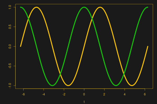
 That means that if you plot the sine wave voltage against the current, the peak of the voltage will be where the current is minimal, and the peak current will be where the voltage is at zero. You can see that in this image, where the yellow wave is voltage (V) and the green wave is current (I). See how the green peak is where the yellow curve crosses zero? And the yellow peak is where the green curve crosses zero?
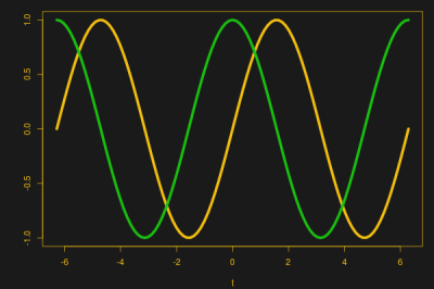
These linked sine and cosine waves might remind you of something — the X and Y coordinates of a point being swept around a circle at a constant rate, and that’s our connection to complex numbers. By the end of the post, you’ll see it isn’t all that complicated and the “imaginary” quantity isn’t imaginary at all.
Continue reading “Imaginary AC Circuits Aren’t Really Complex” →