Complex Impedances Without The Pain

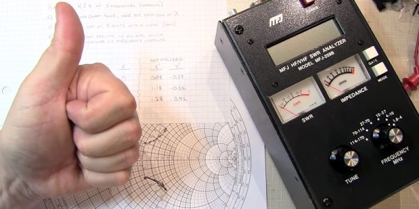
Any grizzled electronic engineer will tell you that RF work is hard. Maintaining impedance matching may be a case of cutting wires to length at lower frequencies, but into the low centimetre and millimetre wavelengths it becomes a Dark Art aided by mysterious and hugely expensive test equipment beyond the reach of mere mortals. A vector network analyser or VNA may be beyond the reach of many, but [Tomasz Wątorowski] is here to tell us about how with some resistors, mathematics, and a bit of lateral thinking its functions may be replicated with a more modestly equipped bench.

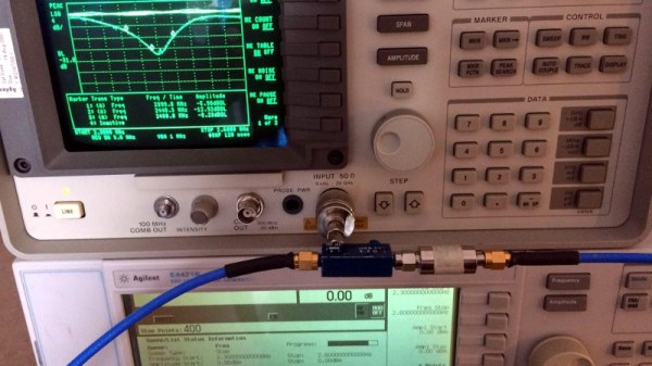
It’s not a method for the faint-hearted as the mathematics are of the variety that you probably learned as an undergraduate but let slip from your memory with thanks after the course ended. The method involves measuring the return loss both with and without a resistor of known value in series with the antenna, these figures allow the real and imaginary components of the antenna’s impedance to be calculated. There is a further piece of work though, this method doesn’t determine whether the antenna is capacitive or inductive. Repeating the measurement with either a capacitive or inductive matching network allows this to be determined, and the value of the appropriate matching component to be calculated.

If you are interested in this kind of work, start with a primer on RF design.

Complex impedance matching using scalar measurements, math and resistors

Sign Of The Smith Chart Times

The Smith chart is a staple for analyzing complex impedance. [W2AEW] notes that a lot of inexpensive test gear like the MFJ-259B gives you complex readings, but fails to provide the sign of the imaginary part of the complex number. That makes it difficult to plot the results on a Smith chart or carry out other analysis. As you might expect, though, he has a solution for you that you can see in the video, below.

A common method is to increase the frequency slightly. In a simple case, you’d expect the imaginary part — the reactance — to go down for a capacitive impedance and up for an inductive one. Unfortunately, this doesn’t apply in many common cases, including when you are measuring through a transmission line which is probably what most people are doing with this type of test gear.

Continue reading “Sign Of The Smith Chart Times”

Imaginary AC Circuits Aren’t Really Complex

If you have ever read advanced textbooks or papers about electronics, you may have been surprised to see the use of complex numbers used in the analysis of AC circuits. A complex number has two parts: a real part and an imaginary part. I’ve often thought that a lot of books and classes just kind of gloss over what this really means. What part of electricity is imaginary? Why do we do this?

The short answer is phase angle: the time delay between a voltage and a current in a circuit. How can an angle be a time? That’s part of what I’ll need to explain.

First, consider a resistor. If you apply a voltage to it, a certain current will flow that you can determine by Ohm’s law. If you know the instantaneous voltage across the resistor, you can derive the current and you can find the power–how much work that electricity will do. That’s fine for DC current through resistors. But components like capacitors and inductors with an AC current don’t obey Ohm’s law. Take a capacitor. Current only flows when  the capacitor is charging or discharging, so the current through it relates to the rate of change of the voltage, not the instantaneous voltage level.

That means that if you plot the sine wave voltage against the current, the peak of the voltage will be where the current is minimal, and the peak current will be where the voltage is at zero. You can see that in this image, where the yellow wave is voltage (V) and the green wave is current (I). See how the green peak is where the yellow curve crosses zero? And the yellow peak is where the green curve crosses zero?

These linked sine and cosine waves might remind you of something — the X and Y coordinates of a point being swept around a circle at a constant rate, and that’s our connection to complex numbers. By the end of the post, you’ll see it isn’t all that complicated and the “imaginary” quantity isn’t imaginary at all.

Continue reading “Imaginary AC Circuits Aren’t Really Complex”