RF filters are really just a handful of strategically placed inductors and capacitors. Yes, you can make a 1 GHz filter out of through-hole components, but the leads on the parts turn into inductors at those frequencies, completely ruining the expected results in a design.
The solution to this is microstrip antennas, or carefully arranged tracks and pads on a PCB. Anyone can build one of these with Eagle or KiCad, but that means waiting for an order from a board house to verify your design. [VK2SEB] has a better idea for prototyping PCB filters: use copper tape on blank FR4 sheets.
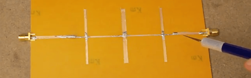
The first, and simplest, filter demonstrated is a simple bandstop filter. This is really just a piece of fiberglass with copper laminated to one side. Two RF connectors are soldered to the edges and a strip of copper tape strung between them. Somewhere around the middle of this copper tape, [VK2SEB] put another strip of copper tape in a ‘T’ configuration. This is the simplest bandstop filter you can make, and the beauty of this construction is that it can be tuned with a razor blade.
Of course, a filter can only be built with copper tape if you can design them, and for that [SEB] is turning to software. The Qucs project is a software tool for designing and simulating these microstrip filters, and after inputting the correct parameters, [SEB] got a nice diagram of what the filter should look like. A bit of taping, razor blading, and soldering and [SEB] had a working filter connected to a spectrum analyzer. Did it work? To a limited extent; the PCB material probably wasn’t right, and board houses are more accurate than a razor blade, but [SEB] did manage to create a 10 GHz filter out of fiberglass and copper tape.
You can check out the video for this experiment below.


Handy for those working with microwaves.
Chefs?
https://www.youtube.com/watch?v=AvDvTnTGjgQ
I was under the impression that FR4 doesn’t have it’s capacity uniform enough to be used for this role…
FR4 is usually ok under 1 GHz, but the first run of any board use slightly longer traces to trim for factory specific materials (the video alludes to this technique). Another mistake is using poor direct toner transfer methods, as the etching process can leave microscopic burrs on trace edges that can haunt the design process.
People like myself usually stick with the dollar ceramic SMD filters/antenna for manufacturing reasons.
;-)
Side note for those who want a working v0.19 repo build process on Ubuntu 16.04 LTS based systems:
sudo apt-get install build-essential libqt4-dev libqt4-qt3support automake libtool gperf flex bison git cmake
sudo apt-get install libxml2 libxml2-dev zlib1g zlib1g-dev
sudo apt-get install build-essential
sudo apt-get install libqt4-dev libqt4-qt3support
sudo apt-get install automake libtool gperf flex bison
sudo apt-get install texlive-font-utils octave-epstk psutils
sudo cpan -i XML::LibXML
sudo apt-get install libgd2-xpm-dev libgd-perl
sudo apt-get install iverilog
sudo apt-get install texlive-math-extra texlive-latex-extra texlive-science texlive-publishers
git clone https://github.com/Qucs/ADMS
cd ADMS
./bootstrap.sh
./configure
make
sudo make install
git clone –recursive git://git.code.sf.net/p/qucs/git qucs
cd qucs
git submodule init
git submodule update
./bootstrap
export LD_LIBRARY_PATH=/usr/local/lib
./configure
make
sudo make install
Teflon/PTFE board is ideal to use, but it’s easier to work with on a PCB CNC mill. For better coupling, you need to go vertical, rather than horizontal, especially at higher frequencies.
Vertical as in perpendicular to the plane of the board?
FR4 will work, but it is not consistent from run to run with the
dielectric/glass ratio. This will cause something like a planar 1 GHz bandpass
filter (copper / FR4) to shift by several (maybe tens) MHz from run to run.
F408 will hold very consistent. OSH Park uses FR408 for their 4 layer service.
I have found this works very well from run to run for a tight microstrip
filter.
Tip for those interested. Look into FDTD (finite difference time domain) if
you want to simulate the frequency response of arbitrary copper shapes / vias
on various dielectric substrates. This type of numerical solution does an
extremely good job if you define the physical properties of the structure
correctly. If you don’t have ten of thousands of dollars for something like
HFSS, there are open-source solutions around like OpenEMS. There is a
java-based front end for OpenEMS that will accept eagle cad files. More info
here: https://github.com/tvelliott/jPCBSim/wiki
I did FDTD simulations of an interdigital line slow-wave antenna at 800 MHz for a magnetic-fusion application a couple of years ago and also warmly recommend this approach. It’s very educational to see the antenna light up with sub-waveperiod time resolution.
Free version of the paper at http://crowscience.com/files/mstlhsims.pdf
The paper is also on ResearchGate: https://www.researchgate.net/publication/261726297_Simulations_of_the_lower-hybrid_antenna_in_the_Madison_Symmetric_Torus_reversed-field_pinch
Re jPCBSim – Is there a secret to getting the animation to work in ParaView? After OpenEMS running for 30 min on the IFA example, the vtp file is only 20K. It opens in Paraview as a single colour mesh with only 1 time step.
Sorted. PEBKAC…
FR4 is okay… It has a higher loss tangent and isn’t terrifically uniform. But it can be used for a lot of things as long as there traces are short.
It is used on most 5Ghz wifi cards…
This with a vinyl cutter is amazing for prototypes.
I don’t care what y’all say, this shit is witchcraft.
He would surely confess when treated with a Comfy Chair!
That is what I said before and even now after the aha moment with my old elmer back in the ham shed, From 50 ohm loading to wacky microwaves all that impedance matching and DC shorted yet at freq open connections, yea RF is voodoo like seeing standing waves demonstrated with sound in water. I still do not have an intuitive grasp of it all but it was instructive seeing a capacitor made with a twisted stub of two wires or how a tuning stub is included in some designs.
https://www.allaboutcircuits.com/technical-articles/learn-stub-tuning-with-a-smith-chart/
The trick, I am told, is to visualize an oscilloscope trace and try to imagine where peaks and valleys land on transmission lines and antennas. I wish I still had access to a copy of the AT&T microwave handbook.
The MIT RAD Lab series is seriously the bible on microwave design.
https://www.jlab.org/ir/MITSeries.html
I have haphazardly dabbled with this stuff in the past, with mixed results. But it might as well be magic for all I’m concerned!
I assume this has to go into a shielded box so that it doesn’t actually act as an antenna and pick up or radiate unwanted signals?
Well, it doesn’t _have_ to. But it’s a very good idea, :)
Stripline filters are pretty much the only way to do filtering and input/output matching in microwave RF world. There are many different configurations, including straight stubs, fan stubs, interdigital filters, comb line filters, and ‘snowflakes’, which are a variant on stubs.
Paul Wade, W1GHZ makes great use of comb and interdigital filters on FR4 with the Local Oscillator and 1296/903MHz boards he has designed for his simple and cheap microwave transverters.
http://www.w1ghz.org/MBT/multiband.htm
FR4 vs teflon makes all the difference in the world. If you need some Rogers or Taconic teflon board, register for pretty much any of the ham radio VHF/UHF/µW conferences and come to the banquet. They are often found on the door prize table. You can also often sample a good size sheet just for asking.
Can I make a tunable comb filter this way, say by mechanical means like a butterfly capacitor? I think I need a nonlinear transmission line, which squashes signals in the time domain so they look like pulses…
You can buy a surplus tunable YIG filter from eBay if you need only one or a few.
Those look really nice, but expensive and above the frequencies I’m interested in right now. I’ll keep it in mind for if I start messing with proper microwave stuff.
I have often encounter comb-like interference, presumably from universal motors, on the lower bands which I would like to filter out before the LNA. It seems like microstrips could be made mechanically tunable. Perhaps they could be rolled up to save space too? Maybe I’m just out fishing… Seemed like a good idea a moment ago.
Quick prototype stripline-like structures are easy to make on double sided FR4 and will work through around 2GHz for on-of examples (at high frequencies the dielectric properties of FR4 boards varies widely between manufacturers, and even between manufacturing batches). What [VK2SEB] is not using are “gimmick” capacitors that allow tuning of the structures manually. A gimmick capacitor at microwave frequencies are just two small pieces of twisted insulated copper wire. You can even make a gimmick inductor out of a loop of non-insulated wire. But the use of gimmick inductors is more difficult, foremost because you have to make sure to NOT short DC paths, and even in DC isolated paths gimmick inductors are more susceptible to “parasitics”.
https://en.wikipedia.org/wiki/Gimmick_capacitor
https://en.wikipedia.org/wiki/Parasitic_element_(electrical_networks)
When you design something like a filter, you should take into account the presence of a variable gimmick. The downside of this is the design is more complex and Q may suffer due to more components. The upsides are that often the inclusion of gimmicks increases the order of the likes of a filter, and that the prototype is easier to “tame”.
That look more like paper than FR4…
Hi bro, Could you send me the simulation of Qucs ?