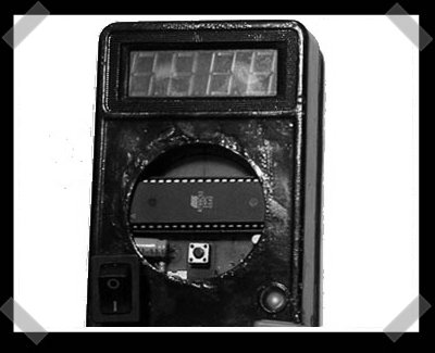
[Wolf] sent in this site a while back, and I thought that this frequency meter how-to looked pretty useful. It’s based on an Atmel AT89C52 and a gutted multi-meter. The circuit isn’t too bad. (The worst of it has to be all the display lines.) The Atmel grabs the signal to be measured and drives the display, so the parts count is pretty low.
9 thoughts on “DIY Frequency Meter”
Leave a Reply
Please be kind and respectful to help make the comments section excellent. (Comment Policy)


This case looks like it was taken out from fire :D
Yeah, she’s taken on one too many gamma rays.
It is pretty ugly. And the range is strange: who needs a 500 kHz Frequency Counter? All the commercial ones reach the Gigahertz range. Which sources was this designed for? 33 khz clock crystals? Everything else than a simple waveform requires another solution anyway…
I don’t like to dump on anyone’s personal projects. IMO these are the kinds of projects that you learn from. However, I’d recommend that anyone who would consider building one to act as a lab counter might be better off visiting a swap meet or a tech company garage sale. Besides, a cheap used analog O-scope is pretty handy for checking frequency.
Measuring RPM’s of rotating equipment would be a perfect use for this.
It’s a cool project, it just needs to have that cosmoline wiped off of it.
just search google for AVR “frequency counter” and you will find tons of better designed circuits that operate up to several hundert MHZ
Home-made 5hz to 500Khz Frequency-Meter? That 500,000hz someone needs check their typo. Because that is way out of the audible range of 20hz-20Khz
Good work there. 500Khz is low but if you’re working on something that low and if it works for you thats fine. Aesthetics could improve.