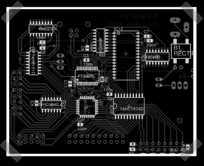
[Ast] sent in his time sampling logic analyser (in German, so use the fish) based on a Atmel Mega8 and a FT232 USB interface and several logic chips. It can store time captures in memory, then upload them to a PC via USB. Looks like a great tool for advanced logic testing.
7 thoughts on “Mega8 Logic Tester”
Leave a Reply
Please be kind and respectful to help make the comments section excellent. (Comment Policy)


Was ist Msps, Kenneth?
At 1:
Its shorthand for megasamples.
Neat project, I have something similar built but without the heaps of logic he uses. I use a CPLD (XC9572XL) for most of the counting and control logic. The only logic part i use is a 74AC245 bus switch.
@ bart
it’s a reference to …
http://en.wikipedia.org/wiki/Dan_Rather#.22Kenneth.2C_what_is_the_frequency.3F.22
no, seriously. I want to know what the msps rate is. most of the decent homebrew logic analyzers will do 1 or 2 msps.
bart, how many msps can your unit do?
@ jimmys
The maximum sample rate of my analyser depends on the speed of the RAM utilised (mine are 15 nS cache SRAM’s 32KiB 8 bits wide), 15ns translates into a theoretical maximum of 83 Mhz, but i more often analyse protocols like SPI I2C, so i use the clocking pin of the SPI bus as a trigger (which is much slower).
This is fed to the CPLD that does all the counting. The design is really simple actually, just a up counter and a few control pins to the atmega of what to sample, divider ratio and input buffer control.
I never tried it at the theoretical maximum, and i doubt actually it will work flawless at that speed. Its built on a protoboard with wirewrap wiring. The fastest i did was sampling the ISA bus of a old 80286 running at 8mhz, i was checking out what I/O addresses it was using.
@ 3 poopoo.
Thanks for the data :-).
This analyzer uses the FT232 for samplingrate generation. The chip is used to output a 24MHz clock which is dived by the counter. The MC then selects one of theses devided clocks or the full 24MHz. This is a really neat design.
In my eyes the analyzer has the following disadvantages:
-If a startcondition is needed it has to be monitored by the slow MC.
-There is no extra logic for different signal levels.
The busdriver of the inputs is an HCT version, so it reads both 5V and 3,3V as high.
But you are right about the startcondition, although it uses the interrupt to minimize the response time and the recording is stopped quite a time before the RAM overwrites it self again, so that the trigger of the startcondition should be in the data never the less.
The maximal sampling rate depends on the speed of the logic-ICs and the RAM.
Theoretically it should be able to be faster than 24MHz, but the FTDI only delivers 24MHz…
But you can use an external clocksource, which might drive the ICs to their limits and you can even choose on which levelchange (H->L or L->H) you want the data to be sampled.