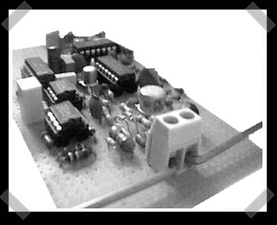
[Andy] sent in this pdf (mirror) describing a simply diy UWB Radar project. It’s not intuitive, but by using a wide frequency range for low power, short distance purposes, the system should avoid interfering with other radio systems. The paper has a complete circuit schematic, and offers some suggestions for adding communications to the signal. Unfortunately, to really tune the thing, you’ll need a kick-ass oscilloscope.


27 thoughts on “DIY Ultra Wide Band Radar”
Leave a Reply to Donald MurrayCancel reply
Please be kind and respectful to help make the comments section excellent. (Comment Policy)


Hmmm… I *do* have a kick-ass oscilloscope.
For use who don’t want to download the PDF:
http://view.samurajdata.se/psview.php?id=3a69542c&page=1
Is it legal to use this band?
Hi your message is good ……But you to have explain it must better…..
Wonderful hack :)
@hypotheel: given the low power involved, the waves are very unlikely to go out of your property. so yes, it’s legal (at least in France), and even if it is not in your country, it will go undetected.
Sounds like the perfect justification for obtaining a kick-ass o-scope!!! :D
Let’s all welcome our latest spammer, _Lalit_ with his asinine “But Proper Information Should Be Needed” comments in all the latest posts.
Come back when you have something to say, spammy.
Now you can detect stuff…sorry can’t imagine why you’d want radar outside detecting velocity and range.
I was hoping this was a wide band scanner circuit.
Regarding the legality, FCC Part 15 rules generally permit transmission in licensed bands without a license as long as you are below 100mW.
In terms of building a scanner, you would probably just want to go out and buy one unless you were doing it for the educational value. I can think of multiple ways of doing it, but I would recommend starting with a regenerative or super heterodyne receiver. Once you’ve built that and got it working, you can play with VCO circuits and feeding say a slow triangle wave into it to make it sweep the tuning.
For UWB, you do not need a license like many seem to think. It’s because the power is below the noise threshold, which is fine by the FCC. i.e. the Radar will look like background noise unless you have a UWB receiver. it will not interfere with any radio system.
Are you kidding me? you have to have a license to use even 10watts. you need to have an even HIGHER class to use 100watts. I had to take the FCC test, its very restrictive.
um, he said milliwatts, not watts. of course you’re going to need a license for 10 watts, you can transmit for miles with 10 watts given you have a proper antenna.
coffeebeans…I believe he meant “milliwatts” (mw) not “watts” or “megawats” (MW). And at 100mw, it’s well below the Federal radar ;)
This sounds interesting, and I already have a use brewing up in my mind…
Any idea on what the range should be?
It seems simple enough to build
rpr1@hotmail.com
UWB is not so much range as data transmission. Range is probably comparable to hobbyist 40KHz sonar sets in range. And the total power is in microwatts, not milliwats. And band power is FAR smaller. Heck, I probably have more RF power in my fillings than this thing does in any particular band.
@Paul Anderson: I know about the FCC rules. I already have high end equipment that can demodulate signals up to 6.1Ghz though.
It’s disappointing though because of all the on chip band hopping in even outlawed equipment. Even high end spectrum analyzers leave out lower ranges and focus on higher, or do the opposite. I know about antenna design interfering, but that’s why they modulate the designs.
When they say “radar” do they mean you could use this similarly to a radar a la military aircraft? I’m assuming this thing allows you to detect the range of an object, and then I guess if you mounted the antenna on something spinning with a complex set up you could have a 360 degree radar. Or is this some other kind of radar that does something completely different that I’ve never heard of?
this is great! I love it!
TheKhakinator: yes, this is good old-fashioned “bounce a pulse off of something and see how long it took to come back” radar. It only detects at a single range, though, because of the way the demodulator/correlator circuit works, so you’d need to sweep the delay value. maybe you could attach multiple demodulator/correlators to the same antenna?
@wim: As mentioned by Mr. Staderini’s description of the delay line: “The 47 pF capacitor in the delay line could be substituted with a varicap diode whose inverse polarizing voltage might be used to change the radar range.”. Alternately, the 1K variable potentiometer could be replaced with one that is digitally adjustable. The step size would probably have to be fine in order to be useful. Just a thought.
hi
njiaj5zaezi4v6lm
good luck
hi
njiaj5zaezi4v6lm
good luck
The author did not clearly state the exact transistors that he used. Will any type of RF transistor work for this circuit?
What type of oscilloscope (what technical requirements) would be necessary for tuning this UWB RADAR?
hello,
thank you
i have a question
can this circuit work for detecting vital sign of human behind the wall for example
No one commented on the question about the no-name transistor types that are shown in figure 4. They don’t need to be high speed transistors, they are used as a noise generator to randomly modulate the pulse generator. The venerable 2N3904 would work fine, or the 2N2222 (or equivalent) would work for this. The critical high speed components are the 74HC04 inverter, the Schottky diodes and 2N5109 transistors.
Hello, I’ve been working on this assembly for 2 years..as described in this publication, the range of this UWB radar is a few tens of cm in the air …. you are right the 3 transistors in common transmitter are a noise generator, which is unique to a UWB radar..it’s a far cry from conventional radio …. i built several copies of this post to turn it into ground penetrating radar, although this one does not penetrate the ground, of not more than 20 cm, but you can detect through a thin partition … it is necessary to increase the power of emission of the output transistor while respecting the timing of pulses nS … for that here I recommend a BFG135 / 235, you will have a finer UWB pulse than with the 2N5109 … the result is to display an identifiable echo on a screen (tablet) … the real difficulty is there … it must be directed towards the Ultra son Arduino radar for the display issue .. if someone who masters the Arduino is interested felt by this challenge, I want to continue this project with him !! ..