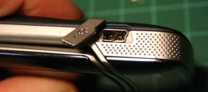
At some point, just about everyone manages to mess up their precious electronics. In this case, someone (not me) somehow managed to totally demolish the mini USB port in their new Motorola cell phone. Surface mount repairs can be challenging without some serious tools, but it’s possible to replace parts without a re-work station. (Guess what I’m getting for Christmas this year.) Today I’ll show you that’s it’s possible to repair a surface mount part with some fairly inexpensive tools.
To do this repair, you’ll need just a few tools:
- fine tip soldering iron (Weller 15 watt)
- Dremel tool with cut off wheel
- De-soldering Braid
- Torx T5 screwdriver
- small flat bladed screwdriver (optional)
- Diagonal cutters
- small hemostat or fine tweezers
- Panavise, helping hands or similar bench top holding device.
I already had all the soldering gear, but I had to track down a new T5 driver since mine vanished. I picked up a decent quality, iron oxide coated T5 driver at Sears for a little over $3. Sears actually has these individually, so you don’t need to buy a set.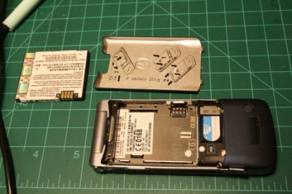
To get started, take off the back cover and remove the battery.
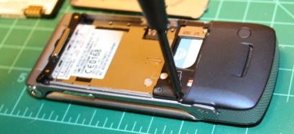
Next, whip out that Torx T5 and remove the screws holding the phone together. On this one, there were only four to remove.
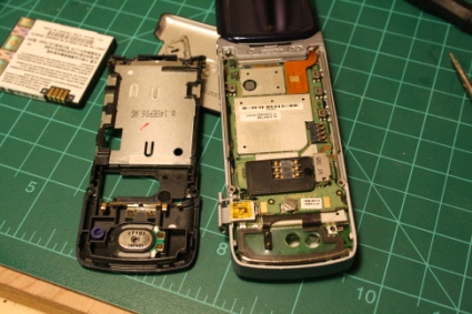
With the screws out, gently pull the phone apart. The lower half of this Motorola clips together, so I gently worked around the edges with a small flat screwdriver until it came apart.
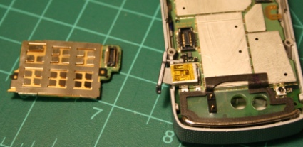
The SIM card board easily separates from the phone via the flat SMD connector. Just gently apply pressure near the connector and it comes right off.
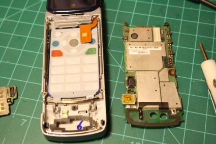
Next, the flat ribbon cable needs to be detached in the same manner, and the main PC board removed from the phone. It should pull right out once the cable is disconnected.
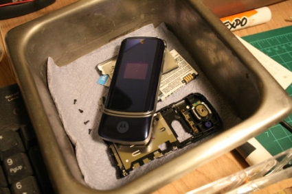
As you disassemble the phone, put each of the pieces into a parts bin. Any sort of container will do, but I’d avoid a static generating plastic Tupperware container.
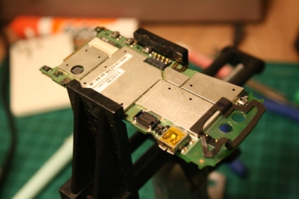
Carefully place the board in your clamp/Panavise/whatever – I had to line up the buttons with the slots in the vise, or I probably would have damaged them when I clamped the board.
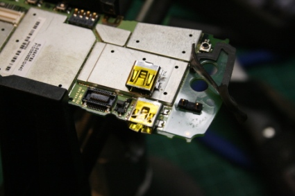
You’ll need a new connector before you can fix anything. I ordered this new SMD mini USB port from Mouser electronics (Part #538-67503-1020). It’s very nearly the exact same part, down to the yellow tape on top.
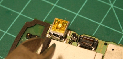
In order to check the condition of the pins, clip the two tabs that hold the rear shielding on to the connector with a pair of diagonal cutters (optionally, you can use a Dremel/rotary tool).
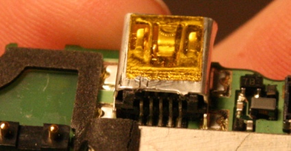
With the rear shield removed, we can access the rear pins – Unlike the front, everything looks pretty good. The advantage of surface mount parts is that they don’t require much solder to hold together. Unfortunately, when you’re replacing a surface mount part, a small amount of solder can keep you from removing the part without damaging the board.
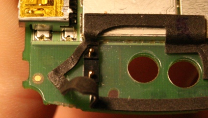
To keep from burning this foam seal, peel it back and stick it off to the side.
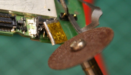
Enter the rotary tool. Sliced the top off of the connector by cutting the sides lengthwise.
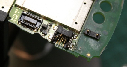
The damage to the pins was pretty amazing once the top was off. Ouch! I went ahead and peeled off that foam seal when I started cutting. Note that the fourth pin is actually shoved inward and upward just a bit.
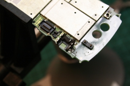
Next, cut across the center of the connector. The bent pins should be gently cut loose and the upper half of the plastic connector will probably fall apart. The shielding on the sides should be cut to allow each leg to be removed individually. (Be careful not to cut the PC board below!)
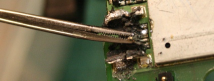
Working from one side to the other, heat up the solder pad on each pin. Then use some tweezers to grip each pin of the connector. (I used a small pair of alligator forceps) If the solder is hot enough, the surface mount pin should come loose with little to no force. It’s vitally important to be as gentle as possible with each one. The solder pads on the PC board are very delicate, and easy to pull up if you’re not careful. Unfortunately, overheating the pads can also cause them to pull up. So be quick about it!
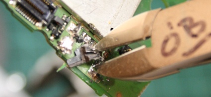
With the delicate pins out of the way, I carefully cut apart the remaining plastic and removed it.
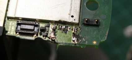
Finally, the remaining legs of the shielding were heated and removed from the board.
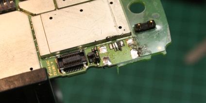
After that, I used de-soldering braid to remove the excess solder from the pads. Not everything came out perfectly. The second to last pad didn’t make it through the removal process. In this case, I’m pretty sure that that pin took some impact when the connector was trashed. I was careful not to torque the pins as I removed them, but I’m not surprised that one pad didn’t make it considering the amazing amount of damage to the port.

The pin in question is numbered X on this Motorola charger pin-out. It’s shorted with a resistor to pin 2 to indicate that a charger is connected. Unfortunately, the phone will never charge from a wall charger again (unless the board is swapped out.) It’s possible that the trace could be rebuilt with a conductive pen, but I’m doubtful that it would be that successful.
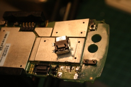
Now we’re ready for the new port. There’s one difference between the original and the replacement: two pins that are designed to align the port on the board. They’re plastic, so it’s an easy fix.

Grind them off with your ro
tary tool so that the connector is smooth on the bottom. After that, clip the tabs on the new port and remove the rear shielding as before.
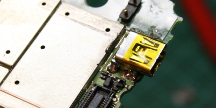
After the new port is aligned (double check the pins in the rear!) solder one of the shielding legs to the board. Double check the pin alignment again, and solder the other legs. Now the port should be solidly mounted.
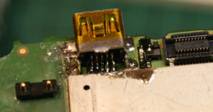
Next, the pins on the new port need to be soldered. The super fine tip on my 15 watt Weller pencil made this easy. Alternatively, you can use a wider tip to solder things and go back over the pins with de-soldering braid to remove any solder bridges. If you forgot to remove the rear shield, you’ll have one hell of a time soldering the pins. On this particular phone, the metal shielding behind the port made it impossible to access the pins without removing the rear shielding.
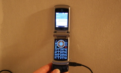
Despite the missing pin, the phone started up just fine when we plugged it in. One more cell phone saved from the recycle bin.


i did the same thing on an external hard drive my younger brother broke, awesome writeup!
http://rpi.edu/~kouttd/03/fixing%20an%20external%20HD.html
-Dane
what rework station are you getting? i’m sure we’ll get to see pictures when you eventually get it.
Does anyone know of an iPod port fix, similar to this? Stupid 3rd party cables….
One problem with reworking smd components nowadays is the use of lead free solder. This means it takes much more heat to desolder the components from the board. Small traces like the ones used in smd are very fragile and wont hold up to high heat required to desolder them for much more than a second or two. One way to fix this problem is by reflowing the solder with something that lowers its melting point making it much easyer to work with. A very simple and cheap way to do this is by just resoldering the part with standard 60/40 lead solder. Also flood the part with a good liquid flux before using a solder wick to remove the solder. Also another good tip is that solder flows towards its heat source. The way I normally desolder something like this is to apply liquid flux to the part. Next I resolder all connections with a medium heat soldering iron (25 watt pencil iron) using 60/40 solder. Then I dip the solder wick in the liquid flux and using new 60/40 lead solder I put a slight amount right on the end of wick while heating it with a soldering iron. Next I place the end of the wick over the solder joint I wish to desolder and very quickly touch the soldering iron on the wick fusing it to the solder joint. next touch the soldering iron to the wick about 1/32 of an inch back from the joint so the solder from the joint will flow towards the heat source (soldering iron). Remember, when soldering or desoldering, flux is your best friend. It prevents your solder from forming a protective oxide barrier preventing it to flow correctly. If after removing all the solder and the component just dosent fall off. Use a #11 hobby knife to gently pry on it while heating each contact to break it loose. Once again, flux everything you touch with a hot iron. For cleanup I have found Goof-Off works great with a couple of Q-tips.
did the same thing on cheap mp4 player with lots of glue after soldering. remember to have some bread handy as surface mount can easily collect too much solder.
Unless you get a female iPod adapter, i dont think replacing the one on an ipod would be easy
Hi, good job on the port changing, made yourself a bit of work there though. If its the first time you’ve done one, then congrats :)
My job is mobile phone engineer, and replace hundreds of sockets a week in every model of phone available. The best way to do Moto mini USBs(since they insist on flooding with solder), is to use dry solder wick(flux on the part or the wick is not needed with a properly heated and tinned iron). Start with the 4 ground pads that hold the USB down(temp around 390c) tin your iron well and with some 3mm wick, apply the iron and if pressure is applied correctly the solder will flow to the wick.
Now leave them still attached to the board(by the remaining solder[very little]) and drop the temp to about 300-320 tin your iron properly again and do the pins 1 by 1.
Now you should have the item still stuck to the board but all the solder gone. Now using a pointy, very sharp scalpal blade poke it under one of the small pins and gently wiggle it under and pop it up. This will leave the pad in place. Repeat with each pin the the ground pads.
Now clean up the pads and refit new socket.
Another quicker, dirtier method is to use the said pointy, very sharp scalpal to cut the pins away from the charging block. Just slide it over the pins until each is cut, take your time and all will be good.
As soon as they are cut and the block is out of the way, tin your iron and gently swipe the iron over the pins towards you. Bingo, all done!
Remember, flux is to help solder flow, putting it on when using wick will help it flow back under the leg of the socket.
I agree with philip on this, very good method for desoldering SMDs. If the part is junk, I just cut the pins off and desolder them a few at a time. Very quick, and very low risk to the board.
One thing that made me cringe from the photos is how he’s using the dremel to cut away the metal, but without a cloth or other means of protecting the phone electronics from the metal dust!
i had done this to a blackberry a while back http://computerguru365.blogspot.com/2006/02/diy-blackberry-usb-repair.html
it can be done to any electronic device that has a usb port. instead of having to buy a replacement i found one off an old digital camera to use.
To #7 andrew.
it made me cringe too, just the very thought of using a dremel was bad enough. I’m lucky enough to own IR rework staion, hot air and a good set of tools, but even without those, a dremel is not needed. But im not dissing the guy who did the job, its still a good job.
@kenny
You could do the same thing to an iPod by buying a broken one. It would be much cheaper than buying another one of those “fashion” statement rip-offs as ones for “sale for parts” are usually only a few bucks I would imagine. I’d hate to screw up on doing that, though.
The easiest way to desolder SMD is to use a product call chipquick that lets the solder stay molten longer to remove the smd. Once you use it to remove smd’s you’ll use it all the time. chipquick SMD removal 1-800-836-2447
http://www.chipquik.com/
ChipQuik!!!! http://www.chipquik.com Works great for SMT removal – replaces original solder with very weak solder – item just pops off. Similar to #6 above, but a specifically designed solder for removal. They offer a sample pack if you’ve got just one job…
Being an owner of the previous version of that phone I’ll just add that the missing “X” connector is quite important.
Now that the phone doesn’t know if it is plugged into a mains charger or not it’ll never charge up from a dead battery state. These phones don’t charge from dead by USB, and they don’t charge at all using those 12V->5V “USB” car adapters (the 12V car plug with “USB” port in the end).
So don’t let the battery get into a state where the phone refuses to turn on, or you’ll be the proud owner of a shiny brick ;)
All of this work, for a Razor?
… it almost doesn’t seem worth it.
Nice work, though.
how is this even hacking news! all i see is the hacking community being dumbed down by making people believe that basic soldering skills make you a hacker.
next maybe we can have a write up on how to hack the gibson.
i have a blackberry with a broken USB port. can i solder on to it with another USB port fro a different model.
Thanks
hi i’m about to repair this usb port on my blackberry pearl. i recently bought the usb charge port and i was wondering what and where can i buy the soldering equipment for this procedure?
thanks
Gawd bless the geeks of todays world!
Ive diligantly searched hi an low thru out the nets and found not olnt the best deals available and a how to here above… Last frieday i got home from work and plugged my Krakberry in the usb charger which i normally use on a daily basis, no more than a few seconds later i smell the appitizing smell of electrical fire… UH WTF!!! and find the Usb port on board muh phone was cooked, the phoone still has all functions except charging… So i weighed the option of replalcing the phone.. and found its cheaper to do the repairs myself.. which im yet to do… and just found this great how too above!
Again Thanks for those who are far geekier than I, i owe you a great deal of respect and perhaps a suggestion… im glad u have a tech like hobby, get laid, it helps being savvy an suave :P
Good article, but my definition of hacking is to try something innovative. Here is how I fixed the mini USB on my cell. First, mini USB contacts do not usually break, they bend – just like in this article. If you think this is your case, read on.
Examine the socket. In the middle you will find a plastic piece. On one side of the plastic there are exposed contact wires, the other side is empty. Insert a small flat screwdriver into the empty half and pry lightly. Almost immediately, the plastic piece will break at the root (deep inside) of the USB socket. Carefully remove the broken plastic.
Now you have access to the exposed contact wires. You can identify the bent one(s). Use tweezers to fix the shape of the bent wire(s). Takes patience, but easier than soldering off the entire USB port.
Once finished, get a good quality adhesive (I used epoxy) and glue the plastic piece back in. You may be laughing at this point but think again. Remember how little power it took to crack the middle piece. I can guarantee that if you use good quality adhesive, the new bond will be several times stronger than the original.
Great tutorial..
This is a reply for james about the dead battery charge problem.
I have had this happen twice now and have found a solution.You have to jumpstart the battery.The foolproof way is to cut open your usb cord and attatch the positive and negative wires to the corresponding contacts on the battery fot about 10 minutes then just plug in as normal and turn it on and hope it makes it far enough in the boot process to charge. Now since I’m lazy I just plug the usb charger in and press the mini usb end directly onto the contacts of the battery at an angle as to get contact. for about five minutes.Then plug it in see if it makes it to charging status and if not repeat adding a couple of minutes to “jumpstart time” keep trying and albeit frustrating it will work after a while.
Hope this helps all with dead battery problems in Moto Rzr phones.
Thx for your information.Visit my blog friend Video Technology Good bye friend.i will come again
Hi. I have a similar phone (Blackberry 8320) with mini USB port pads ripped off. Not just the “x” one as in this tutorial, but all of them. I tried to rebuild them using a conductive pen from CAIG Lab. Not that it would work that well, though…
The pen is too thick for these tiny traces. The paste hardens too fast.
Anyway, I am asking if someone knows a way to test this port without adding the actual mini USB socket. Is there a way to make sure that my traces are good? By measuring resistance between them and making sure there are no shorts and there are connections where they should be?
Does anyone know what resistance should I read between pins 1 and 5, 2 and 5, e.t.c?
Thanks.
I just wanted to add my little input into this discussion. I needed to fix a Blackberry 8320 with mini USB pads ripped out, and could not find anyone discussing it on the net.
So I was able to fix it and this is how.
TRY AT YOUR ON RISK! YOU MAY DAMAGE YOUR PHONE PERMANENTLY.
1) I tried to rebuild traces with conductive silver pen without much of a luck. The traces can be improved, but I could not figure out a way to solder new mini USB socket to them. Once I try soldering, the silver paste just evaporates.
2) However, it is possible to use plated pads that are to the left from the mini USB position. You can find which of the 4 pads corresponds to pins 1,2,3 and 5 (as I recall, the two pads closest to Mini usb are pins 1 and 5 which are +5V and ground and the other two are data pins).
I don’t know the meaning of pin 4. It does not seem connected to anything on this particualr phone
You can buy a mini USB on ebay for 5 bucks and then solder tiny wires in the correct order. It is quite difficult job, and I mixed up pins 2 and 4. After you solder wires make sure you don’t have shorts and your connections are good. Then use superglue to isolate wires from each other on a surface mounted mini USB end. Leave it overnight to dry.
3) As I said I mixed up wires and I realized it after I put superglue on. So, I decided not to try this tedious soldering again, but found a mini usb circuit braker from sparkfun electronics. It is awesome. It allows you to solder your wires in a minute. But the problem is that the PCB is too big to fit into the phone. However, it can be fixed. You need to cut the mini USB circuit braker along the socket using a hacksaw (or better use some power tool with a circular very fine metal hacksaw on it), just along the pads of the circuit. Then you need to file the PCB on the bottom to make it very thin. BE CAREFUL not to damage the traces. The PCB should be about 1 mm thick or slightly less. Then you can file the case of the blackberry in order for this board to be able to fit in between the casing and the metal cover that protects internal circuitry. After that, you will need to cut a larger hole in the left side cover of the phone in order for your socket to be reachable by the cord. And the phone will work again.
hello, what kind of solder paste do I need to use to fix my blackberry curve?? I used one, but it didnt stick on the phone, so I am not sure what I am supposed to be using..
I really wanna learn how to do this type stuff, can u email me a link or something. Wat do i need to do to learn.
Very well done even for a novice I think I could try it
Many of us have chargers from our last celphones just taking space. Their connectors will fit no other cel phones.
Is it possible to buy a mini-USB connector? Then we would clip off the connectors from the older chargers that would not fit any other cel phone.
Then put the mini US-B connector on that charger. And then continue to use the older charger?
Any majopr issues in trying to do that?
Dick
yep. did this on a very expensive htc smart phone.
Couldn’t get the USB working but did get it charging. (in this case the pads were *all* toast)
used wirewrap wire to make new ones, and fed them out through the phone. FWIW one way to make a “ghetto” charger is to obtain two sets of magtrix connectors from maplins, and glue next to each other in convenient places on the case and lead wires to them.
Use convienent polymorph to make a charging cradle with the other halves of the magtrix.
hope this helps someone.
Thanks
I am too much a novice. I have no idea what magtrix connectors are. Is maplins the source?
What is a polymorph?
Can I buy a miniUSB connector? Where? Then clip off the old connector from the charger and replace it with the new miniUSB connector?
Would that be easy? dangerous?
Thanks though for the effort. Maybe I am too much of a novice.
Tech Question:
Q
I have a sprint mogul with a damaged mini charging port. I bought a replacement port and took both to a local computer expert. They could not remove the damaged port with any of there soldering tools. The guy said that the mogul was the only one he has had trouble removing. Is there anyone on here that would be able to do this work reasonably? I really love my mogul. Thanks!
“ChipQuik!!!! http://www.chipquik.com Works great for SMT removal – replaces original solder with very weak solder – item just pops off. Similar to #6 above, but a specifically designed solder for removal. They offer a sample pack if you’ve got just one job…” – Posted at 12:02 pm on Nov 9th, 2007 by Cliff Miller
That ChipQuick stuff looks AWESOME! Thanks Cliff Miller.
Someone can help me?
I’m not a beautiful girl…i tink my TG01 is dead after a short circuit of a car charger, the pins i shorted were the 2-3, i found that was possible use the trick for some chargers.
The phone do not bootup or power-on,i thik the charging circuit burned..
I want open the phone or do someting, like changing MB or repair the circuit.
What your experience say?
Hi, i have a htc hd2 where the micro usb port was damaged. was quoted $350 to get it fixed. I decided not to as it seems like a ripoff. Is the process the same as this original one? I have no experience with this type of thing. ?? Thanks
LMAO what a terrible job replacing that port. Anyone who sees this, DO NOT TRY THIS AT HOME. You will almost def ruin your main board. Instead of buying all the soldering equipment bring it to a certified tech. The Cell Phone Repair CPR franchise is a good one.
Just replaced one of these on an Akai LPK25 MIDI keyboard.. AKAI wanted $40+shipping for the board it was on. $50 can get me a new keyboard, so I tried this before I just replaced the entire unit. Worked like a charm, the trick is patience and being very, very careful when removing the old component. I’ve never done surface mounts before, but I’ll definitely be doing them again. Much easier than I always thought they would be.
I am trying to do is on a wd mybook but the spot where the sheilding legs go has been ripped off. the 5 pins a reok though. I was wonderioing what the sheilding legs are for and if its nessaccery to solder them on.
Great tutorial!
I’m trying to fix a mini-USB connector on my external HDD’s control board right now: found the part on eBay (Mouser is good but shipping to the UK costs a fortune!) and have got the replacement port on firm. Unfortunately, I only have use of a 15W iron with a rather large bit, no spare flux, and it seems that leaded solder is (perversely) harder to get than gold; so trying to pick up excess solder with braid (I’m too poor for a pump) is just about impossible. At present, the solution looks like writing off the whole board and trying to buy a new one from Samsung/Freecom. Damn!
try to melt some new soldering on top of whe old one, then use the braid, it will suck it like a sponge.
Hey man thank you for this, i did not know that i could remove the rear shield from the micro usb connector so i was having a hell of a time trying to solder it again.
Very nice detailed DIY. I remember the days when mini USB chargers were common. It was a bit easier back then. Now with everything going to micro-USB I think that you will find a heat pencil and heat resistant tape invaluable. One of these days I’ll shoot a video of charging port replacement.
My Cell just broke its port. I search on hack a day and find this article, I love you hack a day and contributors!!
My first idea was to do away with the (Li) battery and put on a funky Double-A cell setup with a voltage regulator to 3.7 volts just like the (Li).
would a AA bat. switch out actually work if I had ≥ battery mAh capacity?? (ie 3 AA batteries in series with LDO Vreg)
Thanks, interesting article. Will probably have a crack at mine when I find the parts.
Incidentally the link around the graphic “new-port.jpg” is broken so it reveals the HTML not the image.
SIMPLEST and EAASIEST Solution.
Take a pair of needle nose pliers and pinch in the middle of the micro USB CHARGER/ PLUG (NOT PORT) ever so slightly and insert into port. If this doesn’t work first time, progressively pinch slightly harder until it does.
Go to:
► 1:11► 1:11
http://www.youtube.com/watch?v=Zj5DIOkr0SY
Jul 16, 2012 – Uploaded by avi mendelson
Mobile phone charger fix Many times a Micro USB charger stops charging and this is very …
P.S. I am guessing you will always now have to use EXACTLY this charger with EXACTLY that port. You may have to spend a bit of time tweaking the USB charger end w the pliers as well. Needle nose pliers (maybe tweezers?) are best but you might be able to get away w using the wider regular pliers if you turn them so that only a small CORNER is squeezing the USB plug.
Hope this helps …… it does “mess up” plug for other uses but I found that a small price to pay to render it useable. This worked like a dream for me. I was daunted by other fixes. Thanks, hope I can help even one person.
(This may be posted out of sequence…. if next post is my PS one it should be after this one).
SIMPLEST and EASIEST Solution.
Take a pair of needle nose pliers and pinch in the middle of the micro USB CHARGER/ PLUG (NOT PORT) ever so slightly and insert into pot. If this doesn’t work first time, progressively pinch slightly harder until it does.
Go to:
► 1:11► 1:11
http://www.youtube.com/watch?v=Zj5DIOkr0SY
Jul 16, 2012 – Uploaded by avi mendelson
Mobile phone charger fix Many times a Micro USB charger stops charging and this is very …
(This is my first post …. next post should, of course, be my PS one … had some technical difficulties here).
SIMPLEST and EASIEST Solution.
Take a pair of needle nose pliers and pinch in the middle of the micro USB CHARGER/ PLUG (NOT PORT) ever so slightly and insert into pot. If this doesn’t work first time, progressively pinch slightly harder until it does.
Go to YouTube for visual demonstration. 1:11 Minutes
http://www.youtube.com/watch?v=Zj5DIOkr0SY
[Jul 16, 2012 – Uploaded by avi mendelson
Mobile phone charger fix Many times a Micro USB charger stops.]
P.S. I am guessing you will always now have to use EXACTLY this charger with EXACTLY that port. You may have to spend a bit of time tweaking the USB charger end w the pliers as well. Needle nose pliers (maybe tweezers?) are best but you might be able to get away w using the wider regular pliers if you turn them so that only a small CORNER is squeezing the USB plug.
Hope this helps …… it does “mess up” plug for other uses but I found that a small price to pay to render it useable. This worked like a dream for me. I was daunted by other fixes. Thanks. Hope I can help even one person. …. ( …. sorry but, sometimes I hate technology! ;-) ).
( If not too badly mangled a micro USB charger, this is the . . . )
SIMPLEST and EASIEST Solution.
Take a pair of needle nose pliers and pinch in the middle of the micro USB CHARGER/ PLUG (NOT PORT) ever so slightly and insert into pot. If this doesn’t work first time, progressively pinch slightly harder until it does.
Go to YouTube for visual demonstration. 1:11 Minutes
[Jul 16, 2012 – Uploaded by avi mendelson
Mobile phone charger fix Many times a Micro USB charger stops.]
P.S. I am guessing you will always now have to use EXACTLY this charger with EXACTLY that port. You may have to spend a bit of time tweaking the micro USB charger end w the pliers as well. Needle nose pliers (maybe tweezers?) are best but you might be able to get away w using the wider regular pliers if you turn them so that only a small CORNER is squeezing the USB plug.
Hope this helps …… it does “mess up” plug for other uses but I found that a small price to pay to render it useable. This worked like a dream for me. I was daunted by other fixes. Thanks. Hope I can help even one person. …. ( …. sorry but, sometimes I hate technology! ;-) ).
( If not too badly mangled a micro USB charger, this is the . . . )
SIMPLEST and EASIEST Solution.
Take a pair of needle nose pliers and pinch in the middle of the micro USB CHARGER/ PLUG (NOT PORT) ever so slightly and insert into pot. If this doesn’t work first time, progressively pinch slightly harder until it does.
Go to YouTube for visual demonstration. 1:11 Minutes :
http://www.youtube.com/watch?v=Zj5DIOkr0SY
[Jul 16, 2012 – Uploaded by avi mendelson
Mobile phone charger fix; Many times a Micro USB charger stops.]
P.S. I am guessing you will always now have to use EXACTLY this charger with EXACTLY that port. You may have to spend a bit of time tweaking the micro USB charger end w the pliers as well. Needle nose pliers (maybe tweezers?) are best but you might be able to get away w using the wider regular pliers if you turn them so that only a small CORNER is squeezing the USB plug.
Hope this helps …… it does “mess up” plug for other uses but I found that a small price to pay to render it useable. This worked like a dream for me. I was daunted by other fixes. Thanks. Hope I can help even one person. …. ( …. sorry but, sometimes I hate technology! ;-) ).
( If not too badly mangled a micro USB charger, this is the . . . )
SIMPLEST and EASIEST Solution.
Take a pair of needle nose pliers and pinch in the middle of the micro USB CHARGER/ PLUG (NOT PORT) ever so slightly and insert into port. If this doesn’t work first time, progressively pinch slightly harder until it does.
Go to YouTube for visual demonstration. 1:11 Minutes :
http://www.youtube.com/watch?v=Zj5DIOkr0SY
[Jul 16, 2012 – Uploaded by avi mendelson
Mobile phone charger fix; Many times a Micro USB charger stops.]
P.S. I am guessing you will always now have to use EXACTLY this charger with EXACTLY that port. You may have to spend a bit of time tweaking the micro USB charger end w the pliers as well. Needle nose pliers (maybe tweezers?) are best but you might be able to get away w using the wider regular pliers if you turn them so that only a small CORNER of the pliers is squeezing the USB plug.
Hope this helps …… it does “mess up” plug for other uses but I found that a small price to pay to render it useable. This worked like a dream for me. I was daunted by other fixes. Thanks. Hope I can help even one person. …. ( …. sorry but, sometimes I hate technology! ;-) ).
Can I say that I love you guys for this? I was going nuts trying to find micro soldering tutorials online, but remembered the “wire wrapping 101” I saw recently. So I took a shot at it and searched your database….homerun!