Spot welders are used in the fabrication of automobiles, PC cases, power supplies, microwave ovens, electrical junction boxes, Faraday cages, and various electronics. A spot welder is used because it produces a highly defined point of contact weld. The materials are welded without excessive heating, so working pieces are handled easily. The weld is also highly controlled and repeatable. In this how-to we cover the basics of a spot welder, and then show you how to build one from a microwave oven transformer.
A spot welder’s electrodes serve at least three functions. They transfer electrical energy to the material while also holding it together; this also controls resistance. The greater the pinch force the less the resistance, which results in decreased resistive heating. A lesser pinch force results in increased resistive heating. The electrodes also conduct heat away from the material, while in the off cycles, helping to cool and temper the weld. A resistive spot weld is commonly referred to as a ‘nugget’. Spot welders are generally confined to ferrous materials which somewhat limits their application range. Most produce a weld with low voltage and high current. The welder in this How-to operates from a secondary of 3vac. The primary is 120vac line voltage that should be treated with respect. The low voltage secondary makes the welder very safe, so the electrical shock hazard from the electrode is virtually non-existent. There is however the risk of burn due to the high temperatures as with any welder.
This particular welder is not intended to weld a body panel on your 1966 Jeep; it will not work well on material heavier than 20gauge sheet metal. The intended use is for small projects, for it is not capable of continuous operation. Possible uses are as follows: Welding electrode material for electrolysis cells. Working with the fine components of a vacuum tube. Building a light weight frame for a small robotic platform. Most of us have enough parts laying around to build a spot welder. If you have a microwave oven transformer (MOT) laying around, then you are half way there. On a related note, we had covered a microwave oven arc welder in 2006.

We also needed some heavy gauge copper wire. We used about four feet of 4AWG wire to build the spot welder in the photo. Other materials included scrap 2×6, 2×2, two copper screw type lugs, two copper welding cable lugs, two MIG welder tips, two 4″ x 3/4″ zinc plated corner braces, drywall screws, and three washers.

Pictured above is a working MOT. The first thing we had to do was remove the secondary coils. Namely the high voltage winding, and the low voltage winding. We used an angle grinder with cut off wheel while being careful not to cut the primary winding.

We cut the secondary flush with the MOT laminate core. Both sides of the MOT should be cut. Inspect the MOT for signs that the laminate has been welded. We have found that welded MOTs can handle a little more abuse than their sealed only counter parts. If possible try to keep the core insulation intact, where the secondary will be wound. Though it is not a show stopper if the insulation becomes damaged. The insulation makes it a little easier to wrap the heavy gauge secondary.

After removal of the secondary we had something that resembles the above photo. If the magnetic shunt material falls out be sure to replace it as it was before. The shunt keeps the core from transferring too much power to the secondary. A magnetic ballast if you will. The shunt acts to control the saturation of the core. A brute force project like this relies on such a shunt for proper operation.

Rewinding a MOT with 4AWG is no walk in the park. If you’ve damaged the core insulators, we suggest wrapping a layer of electrical tape in their place. This will help to avoid damaging the insulation on the wire as it is pulled through the core. Our experience is that 3-4 windings is plenty. After all, this spot welder relies on high current and marginal resistance. Not high voltage.

We were careful to ensure that the secondary coil was wrapped in a helical manner to complete the secondary.

We mounted the MOT and 2×2 to the 2×6 base. This particular build used 12″ 2×6 with two 7″ 2×2. These dimensions may or may not work depending on the physical size of your MOT. The only critical part here is keeping the wire length as short as possible.

After the lower jaw was mounted, we also attached the corner braces. It was found that a spare piece of 2×2 as a shim worked well to align the upper and lower jaw. After the upper jaw was aligned we attached it to the corner braces with screws. This formed the hinged portion of the jaw.

The picture above shows the MIG welder tip and the screw type copper lug. This is an improvement from an earlier model we had built. Initially, we used copper tubing with a hole and a piece of 6AWG grounding wire serving as the welding electrode. The grounding wire was held in place by a screw that threaded inside the copper tube perpendicular to the electrode. It was very crude, but it worked. This new method is much more practical.

Here are the two electrodes ready to be fixed to the lower and upper jaws. We double checked the MIG electrodes to make sure they were tight. A loose connection will take heat away from the weld nugget.

Evenly aligning the welding electrodes, we were careful to keep the upper jaw in the natural position where it was mounted. This maintained a flat contact area for the welding electrodes. After we were sure that the electrodes had been properly aligned, the jaws were marked. We then drilled a small hole. Since we mounted with the grain of the 2×2 the holes helped to protect from splitting the 2×2.

With the electrodes mounted, we cut the wire to proper length. We never cut the exact amount we need. We always cut more than we need. This rule of thumb should apply to all electrical wiring. After all it is much easier to cut off excess than wrap a new secondary.

We bent the wires in to the approximate positions in which they were to be assembled and stripped the wire in preparation for the crimp type welding lugs. It is a good idea to strip more than is needed here as well. Simply cut off excess after sizing up the lugs depth. Never crimp insulation with the lug. This will create a potential problem area due to the loss of conduction.

Using a good non insulation crimp tool to secure the wire. We inspected the crimp and gave it the tug test. Simply tug on the wire if it is loose it will pull out. It if doesn’t pull out then an adequate crimp suitable for high current has been made.

The crimped wires were attached to the welding electrodes with screws. We were careful not to over tighten the screws. If a drywall screw had stripped out of the wood, we would have had to use a larger wood screw in its place. After both welding electrodes were fixed to the jaws, we aligned the electrodes. Using pliers we bent the electrodes so that they contacted each other evenly. The electrodes should be fairly close already since they were aligned before drilling.

We opened the jaws and wired the primary to an electrical cord and then tested the secondary. If the breaker trips, check for the following:
- The secondary is shorted (the jaws are closed)
- The magnetic shunts are missing or not properly reinstalled
- Faulty line wiring to primary or shorted primary
- Too much load on the circuit of test or undersized breaker
We observed proper electrical wiring practices. It is also stressed that this is a welder and it should have a dedicated circuit as any other welder would have.

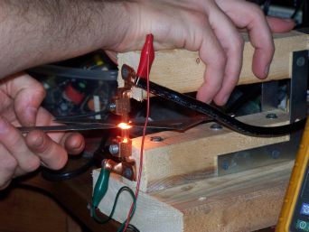
With the power physically disconnected we verified the welding electrode alignment with the material we intended to work on. Before connecting the power and performing an initial weld, we observed a few safety guidelines. This is a welder and will produce very high temperatures. Keep fingers away from the welding electrodes. Allow the material to cool prior to handling. Always wear eye protection. You may be interested in reading about spot welder parameters. There’s also the problem of combustible materials…

This Compaq used very thin aluminum to support the screen and connect the hinges. The metal broke and destroyed most of the lower plastic. We were able to make new supports from 22AWG stainless steel sheet metal. All the welds were made using the spot welder with a special power controller. The power controller will be covered in another how-to.
[youtube=http://www.youtube.com/watch?v=VG1xVNpm7k8]


Hey Guys! First, I am a Professional Engineer, near retirement so I go back to the days where a kid’s first radio was homemade quartz crystal and the only stations were AM. There was NO TV station in my hometown till I was 6. OK, I am an old fart. So I love this, I have traveled much of the world, teaching 3rd world folks how to do things to get/make drinking water with the tools and supplies at hand.
This is a rare and lost state of mind, to find your own way around a need, in the USofA. So I compliment the author and all who are excited at the Idea.
I ran into a medical doc who could not get artificial limbs for amputee children in India. They had been carving strap-on limbs out of wood but these are heavy for kids. He realize there were piles of plastic water and soda bottles around. He now very cheaply purchases solvent, melts the plastic and dips cloth strips in and saturates it in the gummy mix. This is used to hand mold hollow plastic limbs that can be painted to match complexion. These are stronger and lighter than the wood and almost as good as the expensive fiberglass imports.
This project reminds me of many 3rd world shops that I have seen and compliments the desire to do it yourself. KUDOS
For the fella interested in spot welding panels, go to http://www.hackaday.com/209/06/23/how_to_build_your_own_spot_welder
Cute! I used old MOT’s for other things. Thanks for the idea. Might want to keep the turns in line with the primary. I liked the guy who was concerned about shock off a 3 volt secondary! Anyway, going to try this myself for my next amp project. Wind a 30 amp filament xmfr off those old MOT’s. Build a case using a spot welder you suggested…
Look for everyone who critizies this guy, its a HOME BUILT device that will proberly see light work, what it should be built like and how it is built is down to how “anal” the individual is in building of the spot welder, wood is great as its easy to work with and strong, it only conducts current when wet or has a few thousand volts shoved up it, in this welder it will NEVER see that, TV cabinets were made of wood and these had 25Kv generated inside ! I agree maybe earthing the transfomer core is a good idea as if the primery windings cooks and melt plastic core former there is a danger core will become live, other than than I built mine in the same way, used a hacksaw to remove the seconderys and did NOT damage the pri in doing this, infact there is about 1/2 inch seperation between the pri and sec so you would have to be sawing at full speed and not paying attention to cut into pri, if you want a welder that has everthing go buy one !
FANTASTIC!! Article, and great follow-up questions. I too am an old fart that has spent many moons tinkering with electronics. It’s great to see there are so many tinkerers still out there. I can hardly wait to find myself a microwave oven that someone wants to throw away.
Pls how can one produce a spot welder bigger than this with a dimension of (600*300)mm?, i am using it as a school project.pls help me out!!
Man to think I was going to give some tard 500 bucks for a battery welder when I can just make one for free? I’m the tard!
How would you modify this setup to accomodate say a LiPo 18650/26650 cell, where you would be spot welding nickel tabs to the teminal ends of the cells?
I want to build my own battery for an e-bike, and really want to spot weld it.
Thanks
@Harley Watkins: Wrong kind of spot welder.
This’ll kill or seriously maim you if you use it with a lithium batttery.
For batteries you have to use a capacitive discharge spot welder.
They are more complicated and more expensive but cheaper than the surgery you’d need otherwise.
— Nathan
Thanks so much for your caution concerning welding to lithium batteries. I am assuming that the explosion or release of the internal chemicals must be far more serious than that of a NiCad battery. I will take your advice and construct a capacitave discharge spot welder for that purpose. I am posting another question concerning a planned spot welder project using a MONSTER transformer. Maybe you have some advice on my project. Len
That’s funny . I have assembled over 10 Lt-ion battery packs ranging from 12 v 3s5p to 20s 10p electric vehicle packs with my DIY microwave spot welder. Copper electrodes spaced 1/8″ apart
Hey guy . Tell me man that as transformer’s size increases the primary winding decreases or increases. And i have a confusion isn’t dat the primary winding made of thin wire having input from wall socket
i have several transformers laying around, but none of them are MOTs :(
what is special about MOT? could i strip off secondary winding from any other transformer and have a spot welder?
i can see that one of my transformers has primary wound around the core and the secondary right on the primary.
will any stepdown transformer fit the job?
of course with sufficient power.
I NEED TO WORK WITH YOU
As ANOTHER “Old Fart” who tinkered with radio and electricity as far back as 1950 (8th grade shop class), I am appalled and in a state of bodily shaking due to fear of your readers doing something really stupid. Writing about these projects requires some better grasp of English AND logic, as I am confused by the loose use of technically challenging words like “primary” and “secondary”, and NO clear pictures to help. I also do technical photography, after a decade of work in engineering and research labs as a photo/ optics/holography technician.
Hey, guys (and gals): PLEASE go to any library and read a book on basic electricity, and then find an old copy of an ARRL Radio Handbook for more on basic electronics and some really useful theory, even if you are not interested in building a working (and FAA licensed) radio station. Then live a bit longer after plugging in a project to the power socket.
WN8QFR (1958), then W8QFR, now KB8II.
Hi Leonard. Leonard here also. Old fart category myself too I suppose. GREAT advice you offered! I hope people take that into consideration. Please read my post made today. Maybe you can give me a hand. Len
I am eager to begin a spot welder project. A buddy of mine is giving me a monster transformer. 120vac primary and unknown secondary voltage until I get this puppy home. It must weigh 45 to 60 pounds! The secondary is probably very low voltage due to the HUGE secondary terminals/studs. Assuming that it IS what I hope it is and the voltage is something low such as 1 to 10 volts then I think I have my work cut out for me. Here is my question/plan. I think that this will give me MORE than enough current for anything I will want to spot weld. Assuming that, I was thinking of using an SCR or TRIAC at the primary along with a precision timer. I think I already have one that will time from a few milliseconds up to minutes. With that basic thought in mind does anyone have any comments on my basic idea? I’m thinking that if the current is WAY WAY high that it is of little concern if I am able to time it down to a fraction of a second. Correct thinking?? Len
So i would like to build one of these to weld 16g spring steel. Would this design have enough power or do i need to find some way to increase it… Im kind of a beginner to electronics but i want to weld chain links closed for better chainmaille. Please let me know… Any advice would be great
i like your idea it is a very good concept, but there is no technical info like how many out put current what is in put current what kind of braker need to use.also where i can find the microve used transformr.please give me this info
thanking you
Great hack, thank you very much.
What is the recommended fuse rating on the primary circuit?
How much current can be expected on the secondary circuit and how can I measure it?
If I use a clamp-on amp meter rated at 400 amps, will I damage my meter?
Does the wire gauge on the secondary circuit influence the amount of current the transformer will provide?
Again, thank you for the great fun.
What would be the outcome if I wired the primary’s of two MOT’S in parallel, and having wound the secondary’s as described with 4 AWG, connected them to the welder tips in parallel?
That sounds like what is known as a “push\pull” configuration for spot welding.
For the battery tabs you would want to use a series configuration for your electrodes . That would be two small pointed electrodes side by side, instead of an upper and lower electrode, to make contact only on the top work piece. The heat and subsequent weld will only be produced at the two contact points. You’re “growing” nugget from the inside-out. Time, heat, and pressure are the key factors in assuring that the weld stays inside the boundaries of the work pieces. If the electrodes stick, you have went too far.
Good but the efficiency of this invent depends on how much amperes we have to do a better arc or spark to make a nice solder. Try with power supplies batt. chargers, they inducted much magnetic energy.
It was great to know about how to build our own spot welder. I would definitely give it a try. Thanks
Thanks so much for the advice on stud welding! I have been stuck connecting two of the pieces together for quite some time, and this has really helped! I think it is important to take precautionary measures, and to always have safety be number one. This information would be perfect for my uncle Ron! Thanks so much!
Is the coil going to emit an unacceptable level of microwave radiation? The reason I ask this is because microwave ovens are designed to block the radiation from leaving the oven’s box.
In a microwave the only part that produces radiation is the emitter which isn’t part of the transformer.
I built a battery spot welder with a microwave transformer a year ago. Only difference from this one is- I used 4 12g insulated wire in place of the 44g wire. The electrodes are copper rod spaced 1/8″ apart. The arm is hinged with a spring return. Experience has taught me to release the arm at “1000 two” . i cut a slit in my nickel strip at the battery terminals which makes the weld stronger and reduces sticking.
I have made over 10 lt-lon packs ranging from 3s5p to 20s10p
I used cheap batteries from China ( there is no such thing as a Lt-ion battery larger than 3600mah) to learn with. I only fried one.
So I want to make this to weld the rings of chainmail. Rings of 12 and 14 gauge galvanized steel and stainless steel? Do you think this is stronger or should I modify the secondary? What do any of you think? I don’t know much about welding and materials and penetration of such.
Thanks.
I have a few questions.
I intend on using a spot welder like this for welding chainmail rings. 12 and 14 gauge galvanized steel and stainless steel.
First question: Will this be hot enough to weld 14 gauge stainless steel? should i get thicker secondary and make a turn less on the coil?
second: I’ve seen some people twist their own 2 gauge copper wire with smaller strands then simply using electrical tape to sheath it. will the electrical tape melt? how hot does this get?
Third: I’ve kept the electric fan from the microwave oven and am wondering if it’s necessary/suggested to cool the transformer.
thanks