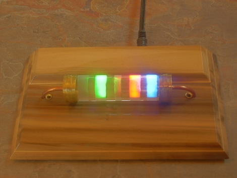
[Darren] built a clock that uses a resistor to display the time. Well, it really uses a model of a resistor. This extremely tardy entry in the Hackaday design challenge houses all of the electronics on a PCB the size of a business card. Four RGB LEDs shine up through holes in the wooden base to light bands on an acrylic tube. The colors correspond to the values used in the Resistor Color Code. In the picture above the clock is displaying 5:26 (that’s supposed to be a red band but the camera didn’t pick it up too well). The band in the center fades up over 60 seconds to signify AM, and down to show PM.
It may be late, but it’s a clever design. It looks sleek and it uses no buttons for an interface. [Darren] sourced the LEDs themselves as light sensors to display the date, and enter time setting mode.


Love it.
Very sleek, now all I need to do is learn my resistors and then build myself one. Or the other way round!
Mowcius
Ah yes, so judging by the fact the ends are gold this clock has a +/- 5% tolerance?
Cool! A simplistic, aesthetically pleasing design which is highly functional!
this is awesome
How do you do black with an LED? Also seems like grey would be just a dim white.
Wow. Really nice idea! I think I have to build one for me, too.
How do you do black with an LED?
Hmm a question that is!
Mowcius
I always read my resistors with a multimeter as I’m colourblind…
I suppose that is a disadvantage to this clock.
That method does mean that you never get your resistor values wrong though!
Instead of a clock, it could be an ohm meter.
I think I like it even more because it was late. Alas I would not be able to tell time with this clock, I haven’t been able to read resistors by color since high school.
Maybe 20Mhz is not enough for this project ;)
WOW !!!
That appeals to my inner-nerd.
I love it !!!
How come I didn’t think of that?!?!
I might have to build one of those.
How many ohms did this take to make? Very nice.
Very nice. looks great. Art.
0 – black – off
1 – brown – dim orange, but could be better
2 to 7 – easy
8 – dim white with a little extra blue
9 – blinding white
The CPU has no problem handling 12 software PWM channels, monitoring the light level on the 10 Hr. blue LED, and timekeeping. The color is 6 bits/channel (18 bits/pixel) at 120 Hz refresh.
I’ll add a video of the time changing sometime tomorrow.
I’m driving 4 RGB LED’s for a PC fan RGB controller (using software PWM), hardware PWM for the fan itself, and a counter for the RPM monitoring. This is run off of the ATMega168’s internal 8MHz oscillator, so 20MHz is plenty fast for 12-channel software PWM (and it isn’t hard to add more channels, I’m using 12 because I only need 12 [4 RGB LED’s]). I’m also using 8 bits per channel (0-255 resolution for each of 12 LED’s) based on Atmel’s software PWM app note.
Very cool
Absolutely wonderful!
I’m building one =o)
@GSV Now,that’s an idea! The wire on the sides of this transistor would bypass the LEDs, and it would change it’s voltage according to the time.
i agree this would work excellently as an ohmeter, it would be cool to see it ‘match’ the color bands of whatever resistor you hook up to it (cool but pointless).
anyway what youve made is very attractive and quite nifty. nicely done!
Of very limited use to me as I’m colour-blind, but as I mostly don’t care what time it is that doesn’t matter. :-)
It’s a cool idea, well executed, and beautifully presented.
Nice work [Darren]
With 10 known settings you could just set up an resistor array and select each preset that way, instead of using a pic and PWM and such, simple logic elements would suffice.
Not that a pic isn’t fine, I’m just saying you could do it even more basic.
It’s funny by the way that using a pic seems overkill in many projects yet we use expensive CPU’s that can calculate billions of floating points calculations a second to write stupid tweets and such all the time.
Or we use Arduinos to flash a single LED arghhh
I meant, other people use Arduinos… I don’t even have an Arduino.
Creative and Original
LOVE IT!
fwiw i “discovered” the LED sensor hack at uni.
they are wavelength specific too, so a red LED responds best to 640nm.
as for the diffuser problem, the best bet for this is to fabricate a shapelock casing on a 3d prototyping machine with suitable castellated structure and epoxy an led onto each piece.
:)
if you use a multi meter to read the value, then you need to make a clock that gives the correct voltages out for the time of the day 12.45 V for 12:45 etc, but i suspect the DVM will not be that accurate :-) maybe using a higher voltage would be more acurate or dangerous
One of the best ideas I’ve seen in a long time
and beautifully executed. Let us know if you
offer a kit (board & parts).