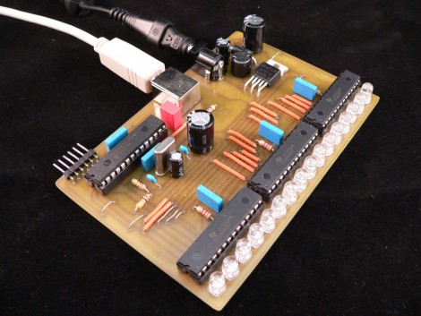
[Simon Inns] turned out this VU meter with a 16 RGB LEDs. He’s using three 16-bit TLC5940NTG LED drivers for the project. They’re not cheap chips but they do a great job. If you were looking to save on parts [Simon] found there’s more than enough brightness and any loss due to multiplexing would not be a problem. The device connects to a computer via USB thanks to the PIC 18F2550 which he’s used in his past VU meter projects. One of the design choices he made was to use a switching power supply. The LM2576 (datasheet) has no problem sourcing 3A at 5V and in addition to two electrolytic capacitors which are commonly used with linear regulators, you just need to add a diode and an inductor.
The meter offers several different configurations which are set on the PC side of things. These include the colors that are used and if the entire bars is used as one meter or split into sections to display both audio channels. Check it out after the break.
[youtube=http://www.youtube.com/watch?v=J3BraNUj2cY]


Here’s my idea… Use the R, G, and B color channels to display three overlapping bars representing low, mid, and high frequencies.
@Tim
Sounds a cool idea but will end up as a psychedelic light effect instead an actual VU meter. People will not be easily able to differentiate low/mid/high frequencies from a composite (RGB) light.
I would however put three rows of filters corresponding to R,G and B respectively side-to-side on top of the leds, to split the low/med/high frequency levels.
Cool, but it seemed nearly always pegged at the limit all the time. Seems like he needs to turn down the sensitivity slightly so less LEDs are constantly lit up.
Those LED drivers can be awfully expensive. (Well, unless you ask TI for samples, then they are free ;))
Instead, you can use your microcontroller to multiplex the LEDs instead. Overdrive them just a bit (but under the LED’s max pulse current rating) to maintain brightness. Be careful though, because this method can make it easy to burn out the LEDs if there is something wrong with your multiplexing code and you keep the LED on for too long!
-Andrew
Those chips aren’t expensive at all, Avnet has them at $1.84
http://avnetexpress.avnet.com/store/em/EMController?langId=-1&storeId=500201&catalogId=500201&action=products&N=0&hrf=www.avnet.com&term=TLC5940NTG
Great project! but it does lack “peak hold” and and sensitivity.. Nothing a few lines of code couldn’t fix!!
Perhaps instead of 3 overlapping bars, make it into a sort of spectrum analyzer with each led representing one frequency band, and its color relating to its intensity.
Beautifull project,
Excellent PC software
Brilliant USB/HID example for using uC with PC
AND IT IS NOT ARDUIno !
i give him a 10
The amount of hifis, mixers etc gets thrown into the trash with far better vu meters/year is fuckhigh. So why dont u just go to the junkyard get some. He calls this expensive hah. I wouldnt pay a 1$ for this trash.
@MrX: I guess it depends on what you are using the meter for… Some people are audio engineers.. To me they are pretty much a decoration. It should be easy to expand the interface to include /all/ of these ideas.
@AnarKIT: yeeeeeeah
@Time: Here it is: http://www.youtube.com/watch?v=wXb3XfN_XKs
i love these TLC chips, i am working with TLC59401 right now :)
they are just grrrreat!
@null
His [and many of hackaday’s readers’] fun is in building and designing these circuits. If yours is in rummaging through rubbish piles, then don’t let us stop you.
Neat! the ICs reflect the light a little bit too.
This is one clean project. Nice work.
I’m not sure just from the video, but I can’t tell if this is actually a VU meter or just a level meter with colors and patterns.
Mike, found your circuit while searching the web.
Decided to clean-up the PCB layout using the four sided board layout, also using a different 5 volt Reg which is now heatsink to the top and bottom side of PCB with feedthrough. The shorten the PCB somewhat. After that made another board using SMT parts instead of feed through holes and DIP’s. If you wish a copy of PCB layout could send it forward.
HEX???
when do i to buy a this?