Saving PIC Microcontrollers With DIY Programmer

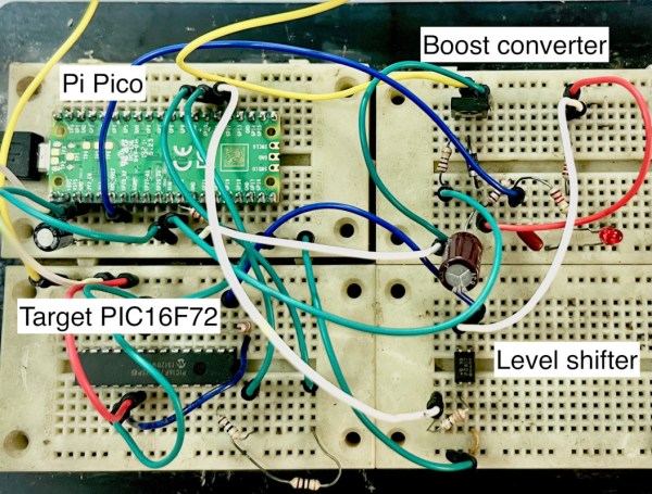
When working on a project, plenty of us will reach for an Atmel microcontroller because of the widespread prevalence of the Arduino platform. A few hackers would opt for a bit more modern part like an ESP32. But these Arduino-compatible platforms are far from the only microcontrollers available. The flash-based PIC family of microcontrollers is another popular choice. Since they aren’t quite as beginner or user-friendly, setting up a programmer for them is not as straightforward. [Tahmid] needed to program some old PIC microcontrollers and found the Pi Pico to be an ideal programmer.

The reason for reaching for the Pico in the first place was that [Tahmid] had rediscovered these decade-old microcontrollers in a parts bin but couldn’t find the original programmer. Thanks to advances in technology in the last ten years, including the advent of micropython, the Pico turned out to be the ideal programmer. Micropython also enables a fairly simple drag-and-drop way of sending the .hex file to the PIC, so the only thing the software has to do is detect the PIC, erase it, and flash the .hex file. The only physical limitation is that the voltages needed for the PIC are much higher than the Pico can offer, but this problem is easily solved with a boost converter (controlled by the Pico) and a level shifter.

[Tahmid] notes that there’s plenty of room for speed and performance optimization, since this project optimized development time instead. He also notes that since the software side is relatively simple, it could be used for other microcontrollers as well. To this end, he made the code available on his GitHub page. Even if you’re more familiar with the Arduino platform, though, there’s more than one way to program a microcontroller like this project which uses the Scratch language to program an ESP32.

Simple CMOS Circuit Allows Power And Data Over Twisted-Pair Wiring

If you need to send data from sensors, there are plenty of options, including a bewildering selection of wireless methods. Trouble is, most of those protocols require a substantial stack of technology to make them work, and things aren’t much easier with wired sensors either. It doesn’t have to be that complicated, though, as this simple two-wire power-and-data interface demonstrates.

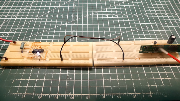
As with all things electronic, there are tradeoffs, which [0033mer] addresses in some detail in the video below. The basic setup for his use case is a PIC-based sensor — temperature, for this demo — that would be mounted in some remote location. The microcontroller needs to be powered, of course, and also needs to send a signal back to a central point to indicate whether the monitored location is within temperature specs. Both needs are accommodated by a single pair of wires and a tiny bit of additional circuitry. On one end of the twisted pair is a power supply and decoder circuit, which sends 9 volts up the line to power the PIC sensor. The decoder is based on a CD4538 dual monostable multivibrator, set up for an “on” time of one second. A trigger input is connected to the power side of the twisted pair going to the sensor, where a transistor connected to one of the PIC’s GPIO pins is set up to short the twisted pair together every half-second. Power to the PIC is maintained by a big electrolytic and a diode, to prevent back-feeding the controller. The steady 0.5-Hz stream of pulses from the sensor keeps resetting the timer on the control side. Once that stream stops, either through code or by an open or short condition on the twisted pair, the controller triggers an output to go high.

It’s a pretty clever system with very simple and flexible circuitry. [0033mer] says he’s used this over twisted-pair wires a couple of hundred feet long, which is pretty impressive. It’s limited to one bit of bandwidth, of course, but that might just be enough for the job. If it’s not, you might want to check out our primer on current-loop sensors, which are better suited for analog sensors but still share some of the fault-detection features.

Continue reading “Simple CMOS Circuit Allows Power And Data Over Twisted-Pair Wiring”

Single Flex PCB Folds Into A Four-Wheel Rover, Complete With Motors

You’ve got to hand it to [Carl Bugeja] — he comes up with some of the most interesting electromechanical designs we’ve seen. His latest project is right up there, too: a single PCB that folds up into a four-wheel motorized rover.

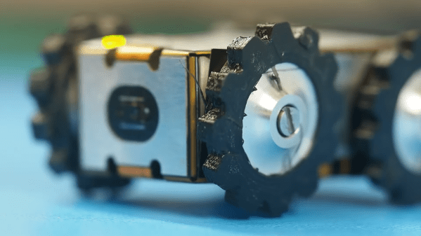
The key to [Carl]’s design lies with his PCB brushless motors, which he has been refining since we first spotted them back in 2018. The idea is to use traces on the PCB for the stator coils to drive a 3D printed rotor containing tiny magnets. They work surprisingly well, even if they don’t generate a huge amount of torque. [Carl]’s flexible PCB design, which incorporates metal stiffeners, is a bit like an unfolded cardboard box, with two pairs of motor coils on each of the side panels. This leaves the other surfaces available for all the electronics, with includes a PIC, a driver chip, and a Hall sensor for each motor, an IMU and proximity sensor for navigation, and an ESP32 to run the show.

With machined aluminum rotors and TPU tires mounted to the folded-up chassis, it was off to the races, albeit slowly. The lack of torque from the motors and the light weight of the rover, along with some unwanted friction due to ill-fitting joints, added up to slow progress, especially on anything other than a dead flat surface. But with some tweaking, [Carl] was able to get the buggy working well enough to call this one a win. Check out the build and testing in the video below.

Knowing [Carl], this isn’t the last we’ll see of the foldable rover. After all, he stuck with his two-wheel PCB motor design and eventually got that running pretty well. We’ll be keeping an eye out for progress on this one.

Continue reading “Single Flex PCB Folds Into A Four-Wheel Rover, Complete With Motors”

Morse Code Clock For Training Hams

It might seem antiquated, but Morse code still has a number of advantages compared to other modes of communication, especially over radio waves. It’s low bandwidth compared to voice or even text, and can be discerned against background noise even at extremely low signal strengths. Not every regulatory agency requires amateur operators to learn Morse any more, but for those that do it can be a challenge, so [Cristiano Monteiro] built this clock to help get some practice.

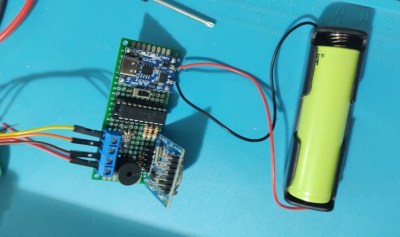
The project is based around his favorite microcontroller, the PIC16F1827, and uses a DS1307 to keep track of time. A single RGB LED at the top of the project enclosure flashes the codes for hours in blue and minutes in red at the beginning of every minute, and in between flashes green for each second.

Another design goal of this build was to have it operate with as little power as possible, so with a TP4056 control board, single lithium 18650 battery, and some code optimization, [Cristiano] believes he can get around 60 days of operation between charges.

For a project to help an aspiring radio operator learn Morse, a simple build like this can go a long way. For anyone else looking to build something similar we’d note that the DS1307 has a tendency to drift fairly quickly, and something like a DS3231 or even this similar Morse code clock which uses NTP would go a long way to keeping more accurate time.

Continue reading “Morse Code Clock For Training Hams”

Nixie Display Module Is Addressable Via SPI

There are plenty of SPI interface screens on the market, but few of them have the charm of the good old Nixie tube. [Tony] decided to whip up a simple three-Nixie module that could be addressed via SPI. 

The stacked construction keeps things compact.

The module relies on a PIC16F15344 microcontroller to run the show, using its built-in SPI interface. It’s built with four stacked-up PCBs for ease of assembly and testing. It uses an internal buck converter to create the 170 volts required for the Nixie tubes from a 6 to 12 volt input. The high-voltage lines are routed towards the inside of the stack to minimize any nasty shocks when handling, though caution would still be advisable.

Driving the display is as simple as sending 16-bit words over the SPI interface, with the device operating in SPI client mode 1. If you’re looking for a simple way to have projects write output to a nice Nixie display, this module could be just what you’re looking for. Alternatively, if you can’t lay your hands on the tubes, there are other pretty solutions out there, too. Video after the break.

Continue reading “Nixie Display Module Is Addressable Via SPI”

Electronic Dice Is Introduction To Microcontroller Programming

By now most of us are familiar with the Arduino platform. It’s an inexpensive and fairly easy way into the world of microcontrollers. For plenty of projects, there’s no need to go beyond that unless you have a desire to learn more of the inner workings of microcontrollers in general. [Cristiano] was interested in expanding some of his knowledge, so he decided to build this electronic dice using a PIC microcontroller instead of the Arduino platform he was more familiar with.

As a result, this project is set up as a how-to for others looking to dive further into the world of microcontrollers that don’t have the same hand-holding setup as the Arduino. To take care of the need for a random number for the dice, the PIC’s random number generator is used but with the added randomness of a seed from an internal timer. The timer is started when a mercury tilt switch signals the device that it has been rolled over, and after some computation a single digit number is displayed on a seven-segment display.

While it might seem simple on the surface, the project comes with an in-depth guide on programming the PIC family of microcontrollers, and has a polish not normally seen on beginner projects, including the use of the mercury tilt switch which gives it a retro vibe. For some other tips on how to build projects like this, take a look at this guide on how to build power supplies for your projects as well.

Continue reading “Electronic Dice Is Introduction To Microcontroller Programming”

Sound Generation Board Makes The Tunes

[Mcjack123] has been getting into chiptunes lately and realized that his original interest started in 2018 when he used an Arduino to turn a TI-84 calculator into a sound machine. His latest iteration is a custom-designed soundboard and he takes us through the design and construction of it in a recent post.

The work models classic sound generators like the 2A03 or the Commodore 64 SID. You have a bunch of simple waveform generators along with filters and modulators to make various effects. These boards eventually gave way to FM synthesis devices like the Yamaha OPL2 and OPL3 chips. All of these cards accepted commands and generated audio on their own. More modern boards are more likely to simply convert digital data from the computer into audio.

Continue reading “Sound Generation Board Makes The Tunes”