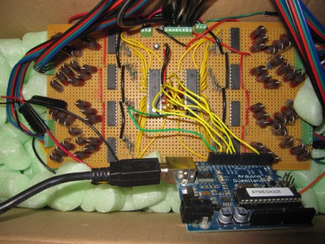
[Thibault Brevet] wanted his own party lighting that pulsed and faded along with the tunes. He ended up building a system based on an Arduino and a PC running Processing. The output from a mixing board is fed into a PC and measured by the Processing script. From there, the calculated light levels are sent to the Arduino to address the LEDs via the control board seen above. [Thibault] built four LED modules that each have two 4-channel LEDs (red, green, blue, white) separated by a few feet. This means 32 PWM signals are necessary to drive the system. To get there, he utilized a pair of TLC5940 16-channel PWM chips, which function like cascading shift registers but have some fantastic current limiting and dot correction features. Take a look at the demo after the break to see what he’s accomplished.
The TLC5940 is a popular choice for driving RGB LEDs, and would be a nice part to use if you decide to make yourself a Ping Pong LED Wall.
[vimeo=http://vimeo.com/17200281]


Very cool, and good work. But i’d like to see the need for the computer removed in a future version.
You’ve offloaded the PWM to dedicated chips, and the audio processing to a computer, what’s left for the Arduino to do? Just translating?
I did something similar with my RGB Fan Controller, used a Processing script to flash the LED’s to music. Using a 20MHz ATMega168 and interrupts I was also able to get 24 channels of 256-level software PWM out of 3 basic shift registers chained together to drive 8 RGB LED’s. I may have to look at this Processing script because the LED fading looks much nicer than what I was getting.
Nice hack… love the perf board!
Schematic? Possible brief explanation of the 4 ULN2004’s?
@ CalcProgrammer1, I would also be interested in seeing a schematic for your project as well.
c’mon, i can’t be the only one that cringed upon seeing those IC’s on non ESD-safe packing peanuts :)
hello!
well i had some issues with the signal level coming out from the mixer so i had to use my external soundcard and first adjust the input level in Ableton Live, which was then sent to Soundflower (Minim on Macs doesnt let you use the line input of the computer, only the mic so i had to trick it with Soundflower)
My point for the future would be a standalone system with only an audio jack input and the animations entirely done micro-controller side. But for now it’s super easy that way to write new animations in the processing script on the computer (strobos effect, lock only one pure color.. whatever, triggered through a key pressed on the keyboard)
@Bill
The TLC5940s use I2C, the computer uses a RS-232 serial port. It looks like the Arduino is just listening for commands on one then repeating them on the other.
@fluidic
Yeah, I figured, I was being somewhat rhetorical in the first post; trying to get the point across that the Arduino is hardly being used.
the tlc5940s use a serial interface but its not i2c. and they need a few other lines to control the pwm clocking and resetting. kudos for getting that figured out. why not a max7313 instead?
currently building a project with the TLC5940 and it is definately not a simple translation, bits have to be clocked in backwards. here’s all the steps for one cycle: http://focus.ti.com/lit/sw/slvc106/slvc106.pdf
I’m impressed by the amount of light generated by 8 LEDs. Awsome
International Dance Party approves
http://www.youtube.com/watch?v=2-JZV5vJzVw
@Bill Porter Re: arduino
Duh, blog cred.
@Eric
Lol, my bad.
yeah mate im doing my major project for year 12 anychance i get get the schematic on this it would be an awesome project!
cheers mate