Phased-array radars are great for all sorts of things, whether you’re doing advanced radio research or piloting a fifth-generation combat aircraft. They’re also typically very expensive. [Nawfal] hopes to make the technology more affordable with an open-source radar design of their own.
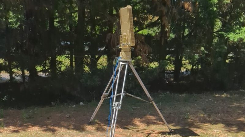
The design is called the AERIS-10, and is available in two versions. Operating at 10.5 GHz, it can be built to operate at ranges between 3 or 20 kilometers depending on the desired spec. The former uses an 8 x 16 patch antenna array, while the latter extends this to a 32 x 16 array. Either way, each design is capable of fully-electronic beam steering in azimuth and can be hacked to enable elevation too—one of the most attractive features of phased array radars. The hardware is based around an STM32 microcontroller, an FPGA, and a bunch of specialist clock generators, frequency synthesizers, phase shifters, and ADCs to do all the heavy lifting involved in radar.
Radar is something you probably don’t spend a lot of time thinking about unless you’re involved in maritime, air defence, or weather fields. All of which seem to be very much in the news lately! Still, we feature a good few projects on the topic around these parts. If you’ve got your own radar hacks brewing up in the lab, don’t hesitate to let us know.


Is that even legal in most of the world? Radio emissions are very controlled in most countries, I imagine that blasting the environment with microwaves is probably not going to go too well.
Good questions! On shortwave, illegal over horizon radar transmissions caused lots of noise (still do).
As a ham I can use the 3cm band 10.0 – 10.5 ghz. We are not authorized to use pulse emission on this band specially. In the US we are authorized to use up to 1500w, but I don’t think it’s a great idea.
He could avoid the spread spectrum of pulses by using a chirp convolved with an envelope and get the detection advantages of correlating. Or just noise and you use a copy of the noise for correlation. I like the noise. It has exactly the same result in correlation as a chirp, which one can prove is the best possible. Chirp I think has far fewer detectable harmonics? I have a book here somewhere on satellite synthetic aperture…….
You’re right to ask. I’m working with regulatory consultants and targeting certification. For now, this is an experimental/research platform.
I am pretty sure you would need a big boy license, not ham license, to actually use this thing. ~160 W pulsed at 10.5GHz
Hams can use 1500 watts up there.
It’s a pretty liberal reading of the ham rules.
Where is there any mention of amateur radio in this or in any of the linked materials? No call sign mentioned either. Found via the linked Hackaday project, he’s an EE in Morocco, so he has no FCC issues at least.
Most (all) countries have laws about what you could (not) do with radiowaves.
In Morocco, the “PLAN NATIONAL DES FREQUENCES” states that the 10,5-Ghz (10,45-10,5) band is allowed for amateur. Not the 10,5+Ghz (10,5-10,55).
I don’t know much about ARRL/FCC and the situation in the US.
But generally speaking: Actually, many “rules” used to be recommendations by nature, originally.
Such as bandwidth of an SSB signal or the band plan,
which says were people are recommended to do what kind of mode.
However, these things were not set into stone.
Amateur radio was intended to be experimental, after all.
In the past, for example, 8 second SSTV was used during normal conversations rather than on a dedicated SSTV frequency.
Also because it had a different purpose.
Sharing images of operator, shack etc instead of sending QSL card-like images with RST reports and 73s.
Anyway. The basic idea behind recommendations was that hams are self-policing and have enough reasoning not to disturb others.
That’s why they are allowed to build and modify transceivers,
the competence had been earned when passing ham exams.
The recommendations meant good and was reasonable often, but its nature allowed for a bit of deviatation.
And there were good reasons, sometimes.
The 3,579 MHz frequency in 80m band was popular because NTSC color carrier crystals with 3,579 MHz were mass produced and readily available.
That’s why man hams used that frequency for all sorts of experiments, not just telegraphy in CW or for QRP activity.
It was useful for, say, r/c remotes/receivers or similar.
Anyway, the main concern for treating them as rules is/was that hams might cause unintentionally interference.
But as long as they were csreful and they didn’t cause trouble,
then everthing was in line with the amateur’s code (aka ham spirit), after all. ;)
That’s my understanding of the matter, at least. 73s
Hopefully your government doesn’t replay with anti radiation, radar seeking ordinance
You might find yourself in “HARM’s” way!
They would make cheap decoys though.
Once upon a time, a great way to cause your opponent to waste an ARM was to take a scrap microwave oven, rip the door off, bypass the door safety, bugger its controls (really easy with the mechanical-timer models, still possible on modern models). When you need to catch some ARMs, leave it out in a field face-up, and activate it with a (preferrably very long) extension cord…
Trading the price of some scrap electronics for the cost of a very expensive piece of ordnance. It apparently worked quite well, at the time.
… or worse, ordnance! ;^)
Very smart for a comment system that doesn’t allow editing.
New to this site ?
Wait to post a reply to a nested comment (you can’t pas a certain level)
“ham” radio license does not apply.
They’re going to need a specific category -> radiolocation license (ie. for RADAR, which is what this is).
Falls under Part 90 regulations, not Part 97.
sounds like description of Starlink dish, wonder how hackable those are
i have pile of old DirectTV dishes — i’ve already used one as a fairly effective audio telescope and would like other ideas. they’re too small for much 2.4 GHz work
You use it as an audio telescope… 3.5kHz sound in air makes for 10cm in wavelength, 500Hz is 69cm. If that works even in the slightest, 2.4GHz will also work to some degree, as it works out to 12.5cm. Standard parabolic reflector formulas will tell you a 50cm dish will produce almost 20dB gain at 2.4GHz.
With a bit of cutting, a satellite TV dish can be turned into a slot antenna for the 2 meter band.
At least not for radar purposes… Uplink and downlink are spaced 4GHz apart, and presuming there are front end filters on the RX side, you’re not going to enjoy replacing over a thousand front end filters.
And your teeth have never been whiter
9 out of 10 beekeepers agree it’s not normal to put honey on your scrotum.
I see this most useful for spotty NEXTRAD coverage…. maybe just below cameras atop cell phone towers in hilly terrain.
Dixie Alley has a lot of hills….and as storms near big radar sites, ground clutter can become an issue.
This is exactly the kind of application I’m interested in. Weather monitoring could be a great use case for networked low-cost radars.
Is there any way to filter out articles like this one that are based on LLM slop? Hackaday writers can’t get enough of it, apparently.
In the short term, yes (go read another blog). In the long term, no. AI passes the Turing test now, so the internet will shortly be flooded with false humans and will have to be abandoned unless you enjoy wasting your time talking to the simulacrum. Turns out that automation devalues the thing it replaces; who could have predicted this?
Only you and I are not AI. And I’m not too sure about you…
;-P
I wonder if this would pick up incoming Iranian warheads and spent stages. We have seen some pretty cool space intercepts right around sundown where it is dark at ground level but space is still sunlit above the Kerman line. like an expanding faint ball and ~30-40 sec later something or a bunch of crap re-entering.
Comment still reserved, despite having been ‘moderated’.
If you can’t say something nice…
Okay, then. The story was an affront to featured contributors, that go out of their way to provide fully painstakingly detailed, freely downloadable content for your readership.
A wishful, vague introduction, 3 or 4 happy snaps, and a non downloadable pdf, don’t constitute a ‘newsworthy’ hack.
You asked for it!
I tend to agree. As soon as I got to “Why this matters” – classic ChatGPT line, I couldn’t help but find myself skeptical of the entire project. Fortunately for me, tat led me to some real learning about his chosen antenna type. I have my doubts about his design because the PCB strips don’t look like the claimed waveguides (that can be etched on a PCB, not just as a full sized waveguide), with no slots. Perhaps this is another type of waveguide, or the “slots” are of a different design. Either way, I learned about what ChatGPT said it was (not using ChatGPT), so that was actually fun. I’m not an RF guy though, so I won’t be able to identify the antenna from the pictures. But taking the desciption at face value, pretending the radiators are at 1/4 wavelength spacing, it does mean its gain direction is fixed. So the phase can be controlled along one axis, meaning it can be steered along one axis only. The description kind of mentions this, but says it “can be hacked” to steer in the other. I suspect that means, rotate the antenna array and you can steer in the other, but lose the first. The entire antenna architecture would need to change to support 2d steering. Those were my main gripes.
Now, if he does have a cheap 1d scanning array that actually works, thats pretty neat actually. Even if it took chaGPT helping along the way. No design files leaves me skeptical. Especially with the whole thing seemingly written as a call for help. So on one hand its like he has a finished project/product, but then also a massive call for help from the basics on up. So I don’t know what to make of this.
HaD has examples of smaller higher frequency lower power steerable radars from widi ships though. So there’s that.
One day I’d like to make a calibratable phased array that didn’t need perfect spacing. The math gets pretty ugly though. 1/4 wave spacing makes everything so nice :)
The github has all the design files. The repo is linked in the project page, but not in the description of the project.
Like you, I was very skeptical of the chatgpt description, but then I remembered Morocco is very much a Francophone country, so there’s a significant chance he doesn’t speak English well and asked chatgpt in French to write an English description for him.
Why I continue to shoot my mouth off, I have no clue.
Thanks for the welcome advice, iraqigeek.
thank you…actually I speak 4 languages (Arabic-French-English-Spanish)….Being a Moroccan citizen I am more comfortable using my native language (Arabic) and French…I obtained my degree in UK…My English is not that bad….I use deepseek to help me generate professional content (I didn’t know that this was a crime )
Great technical eye. You’re right that the current prototype steers in one axis electronically. The ‘hackable’ comment means the digital architecture supports 2D—it’s a matter of adding more front-end hardware. And yes, the GitHub has all the files….I just added a folder named antennas to the github rep (PLFM_RADAR/4_Schematics and Boards Layout/4_6_Schematics/Antennas/)….The idea is to allow to the users to choose between 3 types of antennas
Not Amateur Radio, at least from a legal standpoint.
This is radiolocation, and not merely an FCC matter, possibly most ITU countries.
Likely to attract incoming drones equipped for radar detection.
Might make for a good “fly trap” in that case. Kind of like a reverse Wild Weasel system. Stand these things up to draw in the ARM (anti-radiation missile) and drones then use high speed slew-to-cue guns to knock them down.
So, I guess it would be a combination of a miniaturized Land Phalanx Weapon System (LPWS) to target the incoming drones and these radar sets to draw them in. Heck, an array of these could stand in for the treat detection radar in the Phalanx system.
I’d recommend using an M240 paired with a 12 gauge loaded with magnum buckshot shells. If the 240 doesn’t knock it down the coaxially mounted shotgun starts firing when the drone hits 35 yards.
Actually, none of this directly violates regulations, at least in most of the higher microwave bands. This was what originally allowed EME work, for example.
And one-way, telecommand, telecontrol allowances have all previously been ruled to also allow for reflective ranging (quite a few projects from the 1960s to present).
And Part 5 always exists, if you need more.
(All US-specific, and IANAL)
I no more read any projects on hackaday.io as they all seem incomplete, poorly documented or just rubbish. Iahcaday.io should die.
I see hackaday.io as more of a project log than a place for finished projects. I hate Autodesk but Instructables still does a good job for those.
Your opinion has been noted. Your refund is in the mail.
Thank you to the Hackaday team for featuring my project, and to everyone who took the time to comment—especially those with genuine questions and concerns. I want to address the most common themes directly.
On Legality & Regulations
This is the #1 concern, and rightly so. I am an electronics engineer in Morocco, and I am working closely with regulatory consultants to ensure compliance. The system is being designed with:
Experimental licensing for development and testing
Path to certification (FCC/CE) for commercial versions
Power levels carefully chosen to stay within legal frameworks where possible (the 20km version uses 16x10W GaN amplifiers, but effective radiated power is managed via duty cycle and antenna gain)
For those asking about amateur radio: this is not intended as an amateur radio device. It is a radiolocation system, which falls under different regulations (Part 90 in the US, equivalent in other jurisdictions). I am not claiming it’s legal to operate without a license—I am building it to be certifiable.
On “LLM Slop” & Language
Yes, I used AI to help draft some descriptions. English is not my first language, and I wanted to communicate clearly. The hardware, firmware, and design work are mine—every schematic, every line of VHDL, every PCB trace. If you want proof, the GitHub repository contains the full design files: https://github.com/NawfalMotii79/PLFM_RADAR
On Mechanical Scanning vs. Full Electronic Steering
The current prototype uses a stepper motor for azimuth and electronic steering for elevation. This was a cost/complexity tradeoff to get a working system built. However:
The architecture supports full 2D electronic steering with additional phase shifters and amplifiers
The “hackable” comment means: if you want to build a version with 360° electronic scanning, the digital backbone (FPGA, clock distribution, beamforming logic) is ready—you’d just need to add more RF front-ends and antenna elements
On Documentation & Design Files
Some commenters noted the project seems incomplete. The GitHub repository contains:
Full schematics (in /4_Schematics and Boards Layout)
Bill of Materials
Firmware source code
PCB layout files
Simulation results
It’s an evolving project, not a finished product. That’s the point of open source—to build together.
To the Skeptics
Skepticism is healthy. Radar is hard, and high-power RF is not a toy. But dismissing a project because it’s ambitious or because the creator used AI to write English descriptions? That’s not the Hackaday spirit I know. The files are there. The hardware exists. Judge by what I’ve built, not by how I wrote about it.
A Request
If you have specific technical questions—about the antenna design, the signal processing chain, the regulatory path—I’m happy to answer. If you just want to throw stones, please at least read the GitHub repo first.
Thank you again to everyone engaging. This is how technology gets better.
—Nawfal Motii
It is interesting, has obvious use, and is worth sharing here.
And, a similar approach could be useful for amateur radiocommunication, as well. For that usage, much less precision is needed in most cases.
Even for the radar aspects, adding additional receive-only nodes could allow interesting things (much larger effective aperture, higher precision, etc). Any of the techniques common for long-baseline radio astronomy could be adopted here. And, unlike most radio astronomy setups, the fact that you control the transmit timing would make it relatively easy to “auto calibrate”. Randomly scatter the receive-only nodes around a field, connect them back to the transceiver, ping a reflective target a few times. Let the system solve for phase/delay. Significant improvements in precision and sensitivity for the same transmit budget, and if done carefully, (and with reasonably wide and random receiver positioning), significantly increased resistance against noise sources.
The same effect could be had by networking multiple radar transceivers too, but inter-node communication becomes much more latency/bandwidth sensitive, while surprisingly significant benefits can still be had even with noncritical inter-node communication in the single transceiver/multiple receiver design (it’s similar to multilateration/passive radar research, except that the transceiver can also provide timing and disambiguation that’s not possible in a pure-passive setup).
Do you have any videos showing it in action tracking real flying objects like planes OE drones?
I’m an EE myself. With a project this difficult if there is a not a clear demonstration that it works, I have to assume that it doesnt.
Motivation could be to make money off of pcbway referrals?