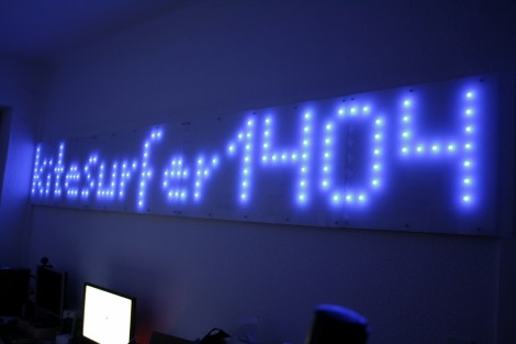
Don’t reach for a sticky note when you need to leave a message for your office mates, write it down on a 12 foot LED marquee. [Kitesurfer1404] built this for his home office, but we’re sure he’ll find fun stuff to use it for. The display has 512 LEDs driven by plain old 595 shift registers for the high-side columns, with an ULN2803A Darlington Array to pull the eight rows to ground. The whole thing is controlled by an ATmega8 via a serial connection. Our compliments to the builder for accurately drilling a grid of 64×8 holes in each hardboard panel of the display. The buses for each row and column also look nice and clean. For the final look a 79% light transmittance frosted acrylic panel was added to diffuse the light.
We used the same method to build our LED pumpkin. Transistors ran the low side, and if we had needed more columns, shift registers are a popular go-to for I/O expansion. Check out that project to learn more about display multiplexing.


Bad Ass!
foot
12 LED display? :-)
I added two videos on youtube. Enjoy!
http://www.youtube.com/watch?v=rfDvs2wmHQE
http://www.youtube.com/watch?v=4prCptKpl8E
He “drilled” it accurately because it’s fricking pegboard. he bought it “drilled”….
You need to fix the title. 12 leds in a display is nothing special.
title fixed, thanks all.
@fartface if you read the page he specifically says he drilled the holes. It’s not pegboard.
@knetcomp ikr? I though the same thing. 2×6 isn’t useful really, and if you’re really good you might come up with a 3×4 alphabet…
lol
Now if this were in a normal office, it should be used to sniff external traffic to sites like twitter and facebook and display your slacking to all your colleagues :)
@kitesurfer1404
if you could take the time to provide a very brief circuit diagram of each of the parts that would be amazing. I know somewhat about electronics but not enough to start this big yet.
@alan look at any LED matrix display. They are all about the same… this is just physically large
@anyone who knows…
would a MAX7219 be better for huge matrixes than using a shift register? or do you still have to use a shift register if you use a MAX7219
@alan
I’m using a max7219 for my large displays (2ft x 3ft per panel, 5×7 pixels). It works great for the first panel, and I don’t have to use a shift register at all (the max 7219 is partially a shift register). However I’m having trouble with signal degradation over the distances from the first panel to the second, which is only about 1m. The third panel doesn’t really work at all.
@Andrew
Oh ok interesting. I was trying to design something that could use multiple max7219. Are you daisy chaining them together? and are you using only 5v for the leds? or 12v?
Yes, I’m daisy chaining them together, and only using 5v. I should check the voltage at the 2nd and 3rd chips to see if that’s the problem. I kinda assumed it was just the signal getting too weak after significant distances; I’m driving the clock and load lines directly from arduino pins, and there is nothing to boost the signal at all anywhere in the line, so the 3rd panel is a couple meters away from the arduino.
I also plan to make a panel that is RGBW, and uses one max7219 per color.
Eh, I tested it again, this time with a mini 5×7 display I made, 2 inches by 3 inches approx, to see if distance really was the issue, or if it was power draw, or something else, and it works completely fine now. interesting.
@andrew
i get a lot of problems at work and cant figure out how to fix them. So i get up and ask a co-worker for some advice. i sit back down like 2 minutes later, nothing has changed, and it works. It’s just the wonders of the universe i guess.
Yea i’m going to try for the RGB idea. maybe i should try with just one color first. would make it a whole lot better.
RGB is gonna be a ton of work. It already took me about 1.5 hours to cut all the wire segments and solder together a single grid of 5×7, it’s gonna take a ridiculous amount of time to do RGB.
I really need to learn how to put these things together for my company
my job depends on it.
Can I the simplest cct diagram of it, so that I can start from there