Decoding The PS/2 Keyboard Protocol Using Good Old Fashioned Hardware

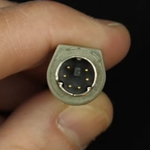
1987 was a glorious year.  It brought us the PS/2 keyboard standard that’s still present on many a motherboard back panel to this day. (It also marked the North America/Europe release of The Legend of Zelda but that’s another article.) Up until this point, peripherals were using DIN-5 and DE-9 (often mistakenly called DB9 and common for mice at the time) connectors or — gasp — non-standard proprietary connectors. So what was this new hotness all about? [Ben Eater] walks us through the PS/2 hall of fame by reverse-engineering the protocol.

The PS/2 connector in all its glory

This is a clocked data protocol, so a waveform is generated on the data pin for each key pressed that can be compared to the clock pin to establish the timing of each pulse. Every key sends a unique set of encoded pulses and voila, the whims of the user can quickly and easily be decoded by the machine.

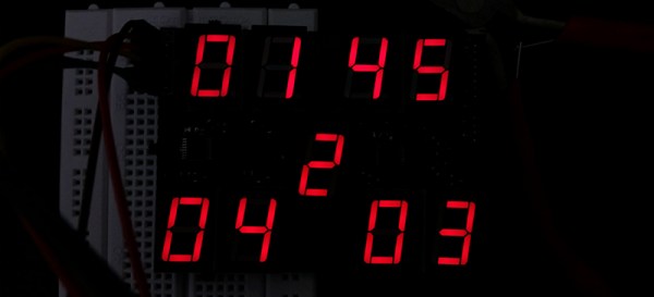
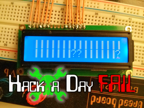
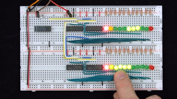
This is where [Ben’s] dive really shines, we know he’s a breadboarding ninja so he reaches for some DIP chips. A shift register is an easy way to build up a parallel PS/2 interface for breaking out each data packet. There are a few quirks along the way, like the need to invert the clock signal so the shift register triggers on the correct edge. He also uses the propagation delay of a couple inverter gates to fire the 595 shift register’s latch pin slightly late, avoiding a race condition. A second 595 stores the output for display by a set of LEDs.

Beyond simply decoding the signal, [Ben] goes into how the packets are formatted. You don’t just get the key code, but you get normal serial interface error detection; start/stop bits and a parity bit as well. He even drills down into extended keys that send more than one packet, and a key-up action packet that’s sent by this particular keyboard.

This is the perfect low-level demo of how the protocol functions. On the practicality side, it feels a bit strange to be breaking out the serial to parallel when it would be very easy to monitor the two signal lines and decode them with a microcontroller. You might want to switch it up a bit, stick with the clock and data pins, but connect them to a Raspberry Pi using just a few passive components.

Continue reading “Decoding The PS/2 Keyboard Protocol Using Good Old Fashioned Hardware”

An Experiment In Shift Registers And Multiplexed LEDs

[Kratz] is working on a WiFi controlled scoreboard, but before building the full-scale version, he thought it would be wise to test out the multiplexing technique for the display. The experiment worked, but unless this scoreboard is for a foosball table, he still has a lot of work ahead of him.

The design of this prototype display is pretty simple, with just two ‘595 shift registers feeding bits to the display. Sixteen NPN transistors are being used to sink and source current to the display. It’s a relatively simple circuit, allowing [Kratz] to fit nine seven-segment displays on a small board with only six wires – ground, two V+ for the logic and LEDs, clock, data, and latch – going to the microcontroller.

There were a few snags in the design; the data is clocked in on a rising edge, but an extra falling edge was required before latching. [Kratz] can’t figure out the reason for this, and it might just be a timing issue.

Fail Of The Week: Reset Issues With 595 And HD44780

fotw-reset-issues-595-character-lcd

We really like to see hardware hackers stepping out of the safe and polished boundaries of available Arduino libraries. One example of this is a project which [Matteo] thought worked: using a shift register to drive a character LCD. This can be a desirable way to do things, because it takes the GPIO usage down from six to just three connections. If you don’t remember seeing that one earlier this month take another look. The gist of it is that [Matteo] hacked one function in the LiquidCrystal library to make it happen.

What makes this a truly great fail is that the problem was not immediately apparent, and is difficult to reliably reproduce. The LCD is unstable depending on how the Arduino board is reset. When connecting the Arduino to a computer the screen doesn’t work until you press the reset button. But press the reset button repeatedly and you get a non-functional screen plus the gibberish seen above.

There’s not much to go on here, but we think it’ll be a lot of fun to state your theory on the malfunction and suggesting for testing/fixing the issue. This could be a lot of things, the controller on the display getting mixed-up, the 595 missing an edge (or something along those lines). Do you fix this with hardware (ie: capacitor to avoid voltage dip), a software issue (need a longer delay after startup), or a combination of the two?


2013-09-05-Hackaday-Fail-tips-tileFail of the Week is a Hackaday column which runs every Wednesday. Help keep the fun rolling by writing about your past failures and sending us a link to the story — or sending in links to fail write ups you find in your Internet travels.

Two-wire Serial Backpack For GLCD Screens

[Debraj] wrote in about his 2-wire serial backpack he developed for a Graphic LCD screen. It’s build on a hunk of protoboard and uses a pair of 595 shift registers to translate incoming serial data to the parallel interface which is used by the LCD screen. It takes more time to push commands this way, but the interface is still quite snappy as you can see in the clip after the jump.

The real trick here is how the hardware has been configured to get away without a third wire for latching the shift registers (if you need a primer on 595 chips check out this feature). The idea of using a latch is that all of the data can be shifted in over the serial pin before it appears on the output pins. Otherwise, the GLCD would see each bit as it shifts into the register, wreaking havoc on its communication protocol. [Debraj] gets around this by using a diode AND gate trick he learned from this other serial LCD project.

One good thing about this method is the 595 chips have a wide range of control voltage that will allow you to drive this with 3.3V or 5V microcontrollers. But you do need to implement the communication protocol and push those commands via serial. For nearly the same cost in chips something like an ATtiny2313 could be substituted to make an even simpler addressing scheme — or even switch to 1-wire protocol. But you’d then lose the wide input voltage tolerance.

Continue reading “Two-wire Serial Backpack For GLCD Screens”

Building A Bigger Bar Graph

Take a gander at the Giant LED bar graph which [Chunky Hampton] recently completed (from this image we don’t think the nick name suits him). It’s simple both mechanically and electrically, but we love the look and think it would be a nice addition to your home, hackerspace, or as a children’s museum exhibit (we’re looking at you [Mr. Porter]).

The enclosure is a hunk of PVC electrical conduit. It’s got to be one of the largest sizes, but still should be found at most home stores. The base mounts easily and the cover snaps into place. [Chunky] used a hole saw to create the openings for the LED modules. They’re circular boards with multiple single-color LEDs on them. A common power bus feeds the high side of each bit, while a couple of transistor ICs controlled by 595 shift registers address them on the low side. From there just use any controller you wish, but in this case it’s an Arduino.

[Chunky] uses the meter to display power output from his stationary bicycle generator. But he also put together a little Larson Scanner demo which you can see after the break.

Continue reading “Building A Bigger Bar Graph”

Output Up To 768 PWM Signals From One Arduino

Here’s an Arduino library that will let you drive a very large number of LEDs. [Elco Jacobs], an electrical engineering student, is the author of the library. He has a work-study job that has him helping out others with their electrical projects and he was constantly being solicited for methods to control droves of light emitting diodes. This was the motivation that led him to produce the dazzling 16 RGB LED example seen in the video after the break.

His setup doesn’t use expensive LED drivers, but instead utilizes 595 shift registers which are both common and cheap. He calculates that it is possible to control up to 96 of these shift registers, each driving 8 LEDs, with reasonably satisfying results. This is thanks to his well-optimized code that manages to drive the clock pin of the registers at 1.33 MHz. This optimization is done by writing each command in assembly, which allows him to precisely count the cycles. Each individual pin takes 12-13 cycles to address, totally 9984 cycles at worst when addressing the maximum number of outputs.

[Elco] thinks this is as fast as he can make the routine run, but he is asking for help with testing. If you think you know how to squeeze out a few more cycles, make sure you join in on his forum thread.

Continue reading “Output Up To 768 PWM Signals From One Arduino”

Shift Register Is All It Takes To Make A 3-wire Serial LCD

This hack is a bit older, but one aspect of the setup makes it worth sharing. Shift registers are a common component to include in a project when you need to increase the number of I/O pins available. We’ve used them to drive LCD screens before, but we never realize you could use a 595 chip to make a 3-wire serial LCD interface. That’s because we’ve always thought of shift registers as having three control pins which must be addressed: data, clock, and latch. But it seems that’s not the case. This hack gangs the pins for clock and latch (called the storage register clock input on this chip) together. This causes the shifted data to be latched to output register one clock cycle after it is shifted into the chip.

This means you can operate the 595 chip with just two pins, but alas, you do need one more connection to drive the LCD properly. This is an HD44780 compliant display. It is being used in 4-bit mode; four of the shift register pins provide that data, while a fifth controls the Register Select pin. Since the shifted data from the 595 appears on the pins after each clock strobe, you must control the Enable pin on the LCD separately or it will behave sporadically.

So there you have it, control an HD44780 display with just 3-pins by using a $0.42 part. Are we going a little too fast for you? Check out this 595 tutorial and give the shift register simulator a try. That should bring you up to speed.

[Thanks Rajendra]