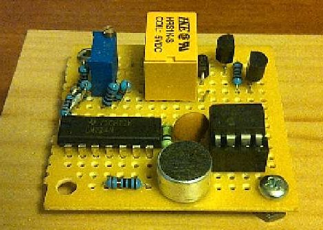
[Patrick’s] latest Instructable walks us though making a clap clap on / clap clap off type of switching circuit, similar in use to that sometimes popular commercial product seen on TV. He does this by using a standard electret microphone, half of an LM324 op amp, a voltage comparator and a PIC micro controller.
The operation of the device is as simple as its wiring, the microphone picks up sound and produces a signal, that signal is stripped of its DC component and fed into the op amp, after 2 stages of amplification the signal passes though a voltage comparator, and if the sound was loud enough a timer is triggered on the pic. Two claps within the specified amount of time, the micro then switches on a relay which can toggle your outside appliance (keeping the load in mind).
On the last page [Patrick] also gives a rough outline of how to make a single clap on / off variant using a 555 timer and some flip flops. Join us for a quick video after the break, and be sure to check this one out.
[youtube=http://www.youtube.com/watch?v=4dA7FjI7nSg&w=450]


Isn’t the clapper used to switch 120VAC lights/tvs and such? This looks like it can only handle 5V.
Its got a Relay
@swighton
“””the micro then switches on a relay which can toggle your outside appliance”””
You could also easily make a double clap with a 555 also… just use a 555 monovibrator triggered on the falling edge of the clap signal to define the valid length after a clap, then AND it with the clap signal.
That said, the PIC would allow for more complex clap patterns, even reprogrammable ones!
Nice useful circuit for PIC beginners to try out :)
My son and I made something almost exactly like this for an “invention fair” last year. His idea was to turn a light switch on when his alarm went off, but in the end, we realized that we’d just re-invented the clapper. Jonathan is right — the double clap can be achieved without a microprocessor. Our needs were simpler — one audio trigger, but a delay before another signal was allowed in. So, dual 555 chips (single 556 really), and some logic gates. Not 555 contest-worthy, but fun nonetheless.
This week’s project(almost a year later) is moving it to a PCB. It’s funny how similar it looks to the picture above.
@Jonathan
I saw the relay, and that it was 5V which I retardedly was thinking was the voltage handling capability of the relay, not the coil rating. I don’t know where my mind was…
“that signal is stripped of its DC component”
forgive me if I’m wrong but isnt the signal stripped of its AC component?
So you’re watching some crappy show on TV and the clapping starts in 7.1 surround and oooh shit the wiring is on fire.
Can this one also be falsed by flipping a nearby light switch on and off?
@jamieriddles
Nope, the microphone overlays an AC signal (voice, noise, claps, etc) on the DC ‘bias’ voltage used to power it.
The AC is what we’re interested in :)
@strider_mt2k
not unless it’s very close, a very loud switch, or the threshold is too low…
Hello,
Can this circuit work for an electric bulb(ac)
please send me the circuit for electric bulb clap clap on and clap clap off switch