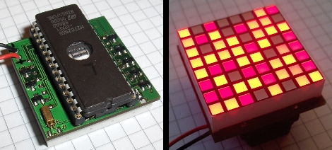
[Konstantin] had some extra 27C256 EPROMS lying around and decided to use them to animate an 8×8 LED matrix. He’s not only using them to store data, but driving the display with them as well. The chip holds 32 kilobytes of data which equates to 4096 frames of animation. A 32 kHz clock circuit works with some ripple counters to scroll through each byte of stored data, turning on the columns while sinking the proper row. Of course current protection is a must so there is a ULN2308A darlington driver and some 2N2907 transistors at work, but you won’t find a programmable microcontroller. Neat!
Yep, you read that right. The picture above shows an EPROM chip that requires a UV light source to erase the data.
[Thanks Kopfkopfkopfaffe]


Very clever.
awesome i have a whole stack of these on my desk at work
It’s interesting to see that he can change the animation speed, but because the lower 3 address bits don’t change, the display will always refresh at the same rate (250 frames/s if i get it right)
That guy has some cool stuff on his site. Like this delta robot: http://www.konstant.in/?cat=6
Very nicely made. I like that the SMD parts fit under the big DIP EPROM as well for a compact module. If you make multiple copies of this module and can distribute the clock without getting significant delays then you can chain lots of them together into a bigger display. Obviously you still get the obnoxious requirement of having to erase these EPROMs with UV though!
The actual idea is pretty old and was how you used to do things like this as cheap easy to use uCs with decent amounts of internal storage didn’t exist back then.
Yes, but that’s not that amazing. I would like to see someone implement some animation sequence using a set of chained shift registers with a certain initial state set through decade counters or whatever.
Been there done that. You can also use them that way to store digital audio and have a microprocessor less audio file playback.
Guys have been doing this for decades people.
One could also use one or two shift-registers in a linear feedback mode.
It would be interesting to expose it to UV light while it’s on and see the data slowly getting ereased
I did a similar project years ago (20yrs ago), as a light controller for my cousins garage band. There was only switches and buttons to program it, the clock was a 555 running around 100ms pulse widths. This allowed us to record a live light show, then play it back. timming was always off due to the slow clock.
Glad to see this type of project!
I wanna see someone scale this up. Something like 320*240 with all the EPROMs tied to a single clock. And playing bad apple.
Some number of years ago the digital logic lab I took in college had you build a microcontroller out of just an EPROM, a counter, and a latch. There were two instructions: “jump to” and “assert”…
Although a few of you have commented that this is not a new concept I think that it’s great to see these hacks using older hardware here on HaD. I’m 24 and this is a completely new concept to me as I came into electronics when uCs were already common place. This is definitely a hack in my eyes – using a piece of hardware for a different purpose than originally intended. And the nostalgic/historical significance is great too.
Pretty cool rig, but programming those old EPROMs, or even EEPROMs is a bit of a hassle if you don’t already have the hardware kicking around. Off the shelf EPROM/EEPROM programmers are pretty expensive last time I checked.
These days, it’s much easier and cheaper to get program code into a microcontroller, and if you need more non volatile data you can always use an SD card or SPI flash chip…
Wouldn’t eight bi-color LEDs per row require a 16 bit bus?
Haha, if a project uses an Arduino it’s overkill, and if it uses an EPROM it’s old news.
I’m very impressed by this one. I’ve always wanted to make something that works with the simplest components possible. This comes as far as I have seen, aside from those mechanical relay computers.
EPROM-based clocks are pretty easy too. You could do a nice one with 4xTIL311s (http://focus.ti.com/lit/ds/symlink/til311.pdf) and a 16-bit EPROM. Since the TIL311s can decode to hex, maybe change an upper address line to flip between counting time normally or in hex :o)
You couldn’t lay out once again distributing of a payment and program EPROM Display
Thanks!
In the article there is a misspelling: “turning on the columns while sinking the proper row.”
Sinking should be spelled Synching or Syncing
No, it means current sinking, complementing current sourcing. Or in other words, “connecting up the negative wire”. It’s how grid displays are usually driven.