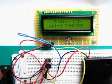
This hack is a bit older, but one aspect of the setup makes it worth sharing. Shift registers are a common component to include in a project when you need to increase the number of I/O pins available. We’ve used them to drive LCD screens before, but we never realize you could use a 595 chip to make a 3-wire serial LCD interface. That’s because we’ve always thought of shift registers as having three control pins which must be addressed: data, clock, and latch. But it seems that’s not the case. This hack gangs the pins for clock and latch (called the storage register clock input on this chip) together. This causes the shifted data to be latched to output register one clock cycle after it is shifted into the chip.
This means you can operate the 595 chip with just two pins, but alas, you do need one more connection to drive the LCD properly. This is an HD44780 compliant display. It is being used in 4-bit mode; four of the shift register pins provide that data, while a fifth controls the Register Select pin. Since the shifted data from the 595 appears on the pins after each clock strobe, you must control the Enable pin on the LCD separately or it will behave sporadically.
So there you have it, control an HD44780 display with just 3-pins by using a $0.42 part. Are we going a little too fast for you? Check out this 595 tutorial and give the shift register simulator a try. That should bring you up to speed.
[Thanks Rajendra]


Better yet, use a 74HC164 which doesn’t have the latch register, only the shift register. The benefit of this is that the output won’t be one bit behind the shift register as is the case when you use the 74HC595 in the manner described above.
Iep, i never understood people paying for serial lcds. I’ve used this method a couple of times.
And don’t forget that a 74HCT595 powered at 5V accepts 3.3V levels so that you can control a 5V lcd with a 3.3V microcontroller.
This isn’t a true 3 wire interface if you add the power lines. Take a look here for a true 3 wire LCD : http://romanblack.com/shift1.htm
There was a very old article by Mike Predko describing this:
http://www.rentron.com/myke1.htm
Agree with bogdan and spiralbrain. I have my LCDs hooked up this way and use the latch of the SR. The 3 wires it takes is better than the six but it’s still not a one wire (nor did it claim to be) interface.
this method is however more code efficient than using the latch since you don’t have to shift out the data twice (once with EN low and once with it high). it’s also less timing sensitive than the one wire method above. I think I might change my setup if I wasn’t so lazy.
Nice work.
I’ve used it with the EN pin of the LCD connected to the output of the shift register. The shift register gets connected to a SPI interface. This simplifies software quite a lot, you basically need to write the data to the SPI register, not a port. (of course the CS/EN pin needs control, but there’s no big deal).
The method with the RC filters if good, but really only in extreme cases of necessity. It is very sensitive to timing and component value variation with temperature.
42 cents for a 595?! Try Jameco, or Ebay and get a pack of 10. I’m still learning, but having a lot of fun with this part.
And thanks very much @dood for the informative link. I’m sure there’s a goldmine of information in those PIC books that hasn’t completely found it’s way into the Atmel and especially the Arduino communities.
OK Ive bought a shift register. It comes in a little black chip. Which bit makes the LCD now?
Or should the title read “what it takes to drive an LCD” ?
Pedantry over, normal service can resume.
I’ve done this before using SPI on an ATmega before with a 74HC164. Nice thing is, the SPI hardware takes care of all the clocking and sending data for you, so all you need to do is write to a register and let the chip take over.
If you wire your setup correctly, you may even make a true SPI slave out of the LCD [the best way for this though is to use another chip in slave mode driving the LCD directly using a parallel interface].
Aaaaaaaargh! What’s that? The sound of countless Arduino drones crying out in realisation….
lol
for what reason i got thanks from you?