After reading over the proceedings of the 2005 SIGGRAPH, [Dan] realized he could reproduce one of the projects with $50 worth of equipment and some extreme cleverness.
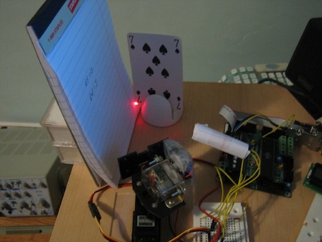
[Dan]’s dual scanning laser camera operates by scanning a laser across an object. The light reflected from the object illuminates a flat surface, and this light is measured by a photocell. After measuring the resistance of the photocell, an image can be reconstructed from the light reflected off the flat surface. The result is quite ingenious, and we’re very grateful [Dan] gave us a great walkthrough with the code and theory of operation.
The project was covered in this Slashdot story a from a few years ago, and we’re surprise no one has bothered to cobble this project together. It’s a very simple build – two servos to control the x and y axes of the laser scanner, a photocell, and an ATMega board. Dan says the microcontroller isn’t even necessary, and this ‘remote imaging’ could be done with an ADC hooked up to a parallel port.
[Dan] was kind enough to to give us a video of his contraption in action. A very nice build from a very accomplished guy.


video link dont work
i download it by click on it
but no video play or download
I once considered this technique as a way to build a scanning optical microscope, with mirrors mounted on piezos as the scan. Such a machine should be capable of extreme deep depth of field compared to normal microscopes, and still limited only by the wavelength of light. But I never got around to trying it.
Hmmm, blue laser diodes … hmmmm…
@ferdie, it works for me online (in Firefox) and downloaded and played in Quicktime.
Here’s the original concept:
http://www.youtube.com/watch?v=p5_tpq5ejFQ
Cool stuff!!
Man that video is way too cool.
amazing :)
does it means you can get a 3D render of the scene
with one camera and a projector?
(picture from both angels = stereo vision)
it can do diffuse-diffuse reflections, but how about diffuse-diffuse-diffuse?
I don’t get it. This is just a very slow flying spot camera (albeit with the light indirectly bounced off another surface) – so what? John Logie Baird et al were doing this to create television pictures in the late 20s/early 30s.
The 20s and 30s had their cool moments, too.
The last part of the video Brett posted looked like something out of CSI’s ‘magic box’, you know, the one that they can plug their computers into and ‘enhance’ images. :p
@axodus
I doubt it, this process looks at an image from 2 different angles, but our eyes look roughly parallel to on another and depth is created through parallax.
Also, if it were possible it would be impractical, as it would take several seconds to image each frame.
Slightly disappointed. Was expecting something more like this… http://www.cl.cam.ac.uk/~mgk25/ieee02-optical.pdf . This method picks up diffuse reflections of monitors (CRTs in this case) and reconstructs images of the screen.
I’m not sure if I see a purpose to this method especially if it requires you to have an emitter in the same location as where your sensor would have to be.
Nevertheless, still interesting.
replace laser by IR thermometer and adjust the code to convert temperature to a color, and you’re my man ;)
You can get IR 0.02 C accurate chip thermometers, iirc they are in a 4 pin package and sold by Sparkfun.
The only problem is that they are a bit of a pain to interface to, however someone has written working code which runs on the PIC 16F series.
Wonder how reflective the mirrors on a typical DLP chip are at thermal infrared wavelengths?
@bothersaidpooh using a DLP chip, now that is a great idea, far more elegant than my idea of using servos.
Indeed, I have no idea if the chip actually reflects 8-20 μm wavelengths, but this is certainly an idea which is worth messing around with!
Now the hunt for an affordable dlp development kit begins ;)
Thanks,
NGB
Nice setup.
Its only half correct if I recall the original paper correctly.
The idea was to read the back of the playing card that was invisible to the light source and the camera. Here you’re bouncing the laser off the card which is cheating.
Still, very net. I’ve never imaged something using servos and a laser pointer before. Very cool.
Said it before, say it again: Why do people insist on only reading in one direction instead of simply reading left to right then moving the laser up a bit then right to left, and repeat.
Seems so odd and forced by antiquated convention that is not necessary anymore, it’s very simple in software to just write it out in 2 directions surely and a flyback is not needed for a slow scan.
@Whatnot,
Ive had a bit of experience with AFMs, and the researchers are now using cycloidal (spiral) scans rather than raster scans. There is no abrupt changes in direction and scanning speed is at least 50% faster.
Nothing new here. Back in the old days when computer monitors and televisions used CRTs, the government used to see what people were looking at on their computer and TV screens by imaging the light level of the window curtains, as illuminated by the raster-scanned CRT phosphors. A telescope and a photocell is all it takes (and color filters if you want a color image). You need to clean up the composite sync with a Phase-Locked-Loop as well… LCD screens make this a little more difficult. ;-)