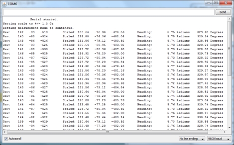
The folks over at LoveElectronics recently published an article that explains some of the ins and outs of magnetometers for those who are interested in trying one out, but might not understand how to use them.
A good part of the article focuses specifically on how to manipulate the HMC5883L magnetometer from Honeywell, but a lot of the information can be applied to other makes/brands of compass sensors. They start out discussing in very basic terms how the compass works, then delve into some specifics on how to interface the chip with an Arduino, courtesy of a breakout board that they sell. The breakout board is actually quite simple, so any number of custom iterations could be built for your own testing purposes.
They walk through the use of an HMC5883L-specific Arduino sketch they produced, making it easy for beginners to start getting useful data from the compass units. While a pre-made sketch might seem like a bit of a cop out, it at least gives the curious/motivated beginner a chance to look at some completed code in order to see how things work.
If you are interested in cutting your teeth on some additional beginner concepts, check out these other how-to articles and tutorials.


Android phones come with a 3-axis magnetometer standard. Along with a 3-axis accelerometer, and many other sensors.
The API for accessing the sensors is incredibly simple and great for beginners.
Hi Mike,
Thanks so much for publishing my tutorial. I hope people can find it useful. I’m people let me know I’d be glad to a tilt compensated version about how to correct for a badly orientated compass.
Thanks,
James (Love Electronics)
James,
I am having a great deal of trouble with the library code – is it posible that IDE 1.0.3 in some how not complient?
The USGS has a nice site about magnetic declination. There’s a downloadable calculator, data, tutorials etc. Look here:
http://geomag.usgs.gov/
and here…
http://geomag.usgs.gov/software/baseline/equations.php
@Drone
Great source! I shall definitely include that information in my next tutorial with a tilt-compensated implentation.
Ha, what a coincidence. I ordered this exact chip on a breakout board a couple of weeks back but haven’t had the chance to play with it yet. Nice find, I’ll be sure to bookmark this one.
We have used magnetometers in our project. We have found that when we rotate the sensor the readings are in a circle (or sphere when rotated in 3D). But the middle of the circle is not 0,0! So it is important to calibrate the magnetormeters on the site where you use it.
The process:
* Attach your magnetometer to its final place (your vehicle may have a constant magnetic field)
* Do some turns with your vehicle (we have done it in 2D, but 3D patterns may also work)
* Draw the measured points. They should align with a circle.
* Find the center of the circle. Save the coordinates.
* When measuring the heading you have to count with that the heading is relative to the middle that you have previously measured! So substract the center coordinates from what you have measured before counting atan2 to find the heading angle.
We have used magnetometers in out project: http://qgears.com/luke
Sorry it is not well documented but the video may be interesting.
Me thinks that those sensors are great if a little pricey, but a LOT cheaper than the ones with integrated accelerometer.
£21 isn’t bad when the whole board weighs so little, good luck trying to implement a triple axis sensor in hardware although I did kludge a single axis one together using metglas rolled up and wrapped in thin wire.
They should make a “Vinculum” board, with all their sensors on a single PCB with integrated arduino to save a lot of wiring :-)
(apologies to Paramount for ripping off the BORG)
Original link broken, archived at https://web.archive.org/web/20130624080828/http://www.loveelectronics.co.uk:80/Tutorials/8/hmc5883l-tutorial-and-arduino-library .