Pulse Width Modulation is definitely the preferred method of dimming an LED with a microcontroller, but we were interested in hearing about a different method called Binary Code Modulation. BCM does the same thing as PWM, it turns the LED on and off very rapidly so that your eye cannot detect a flicker. The brightness level is a result of the average amount of time the LED is on versus when it is off. This is called duty cycle and although it can be the same percentage for both PWM and BCD, there is a fundamental difference.
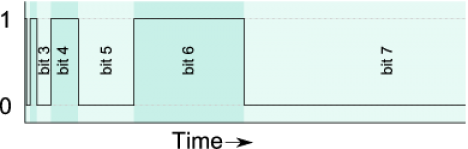
While PWM usually uses a cyclical on/off cycle (30% on, 70% off, repeat) BCD uses a cumulative cycle. As you can see above, each successive bit of binary code carries double significance compared to the previous bit. Now just assign a duty cycle based on your precision, and have an interrupt fire for each bit of the counter. The graph above shows some highs and some lows combining to reach the target duty cycle. An interrupt is used for each bit, and pin changes are made in the service routine.
The benefit of this system is that it is scaleable without adding overhead. You’re already running the interrupts so servicing 8 or 128 LEDs doesn’t have vastly different needs as it would with PWM. The big downside is that the more bits of precision you use, the faster your processor must run so that the eye doesn’t detect the lengthy on or off cycles of the higher bits as visible flickering.
Thank you [Yetihehe] for tipping us off about a link that [Tomas Martinsen] left when commenting about an Arduino library for up to 768 PWM outputs.


Don Lancaster’s magic sinewaves might be good to use for this too.
This seems pretty smart. Never heard of it either. Thanks HAD!
This is how I do it, didn’t know it was a thing
I don’t know nuttin’ about nuttin’ and I’m barely qualified to even read this site much less comment, but I believe that “duty cycle” is the fraction of time on compared to the total time, not compared to the time off. So a device that is one half the time would have a 50% duty cycle.
That’s correct. What’s your point?
My immediate reaction was “there’s no way your processing doesn’t scale with the number of LEDs!”
And I was right. This method *does* reduce the amount of processor time generating the PWM signal, but the processor time still scales with the number of LEDs. This approach transfers the workload from the ISR to the main function–all the ISR does is look up an element in an array, dump it onto PORT pins, and change its own maximum value. The main function calculates the values which the ISR will use. (interestingly, it seems like the calculation is basically a matrix rotation)
BAM alone is great for reducing the computational load of software modulation of LED intensity. However it has some nasty artifacts when the modulation is dynamically changed (e.g. fading). Consecutive intensity level changes that change a significant bit can introduce a visual glitch that is very noticeable. A group figured out a clever solution here:
http://www.picbasic.co.uk/forum/showthread.php?t=7393
You just implement alternating BAM periods with the bit order reversed in each period. The creator dubbed it “BAM-MAB” – sure to annoy the author of the article mentioned here.
wow! That was a great tutorial!
Thanks a lot
i don’t get what this method is supposed to achieve. it is basically a slow pwm, with the frequency determined by the upper bit and the lower bits introducing upper harmonics which don’t improve the sampling rate.
Nice. But is there a different system, where e.g. a 50%50 duty cycle actually flips every bit, while a 25%75 duty cycle will fill every 4th bit? That would minimize flickering…
Yeah, it’s called regular PWM. AVRs can do it in hardware with a counter.
Actually sounds more like pulse density modulation, which is fixed-length pulses spread out across the period and puts more of the ac signal at higher frequencies than pwm.
@tantris: this is a method for controlling many pwm outputs without devoting all your processor cycles to the problem. Typical processor utilisation is about 6% for 20 leds with this method.
Very interesting method.
My ShiftPWM library uses 5.4 clockcyles per pin each interrupt in the latest version. (elcojacobs.com/shiftpwm).
This would use a bit more cycles, but only needs 8 interrupts instead of 256. Actually you only have to copy the bits from the duty cycle setting to the outputs and hold it for 2^(bit position). It gets a bit more complex because the time between interrupts is not constant anymore.
If one is using this for LEDs, and is also doing gamma correction, might it make more sense to use base-gamma coding, rather than base 2?
(Gamma Code Modulation)
Using gamma correction limits my pulse lengths to a subset of possible pulse lengths.
(One posting suggested needing 10-11 bits of PWM precision to encode 256 levels using a gamma of 2.5).
If I select my pulse fractions based on powers of gamma (gamma^0, gamma^1, gamma^2, …) then each possible brightness value will be encoded as a 1 in the apropriate place, and 0’s in the rest.
(Said another way – any brightness will only use one of the cycle lengths).
* If gamma is >2, gamma code modulation would use fewer interrupts (e.g., 256, rather than 1024 in the above example). (Of course if gamma is <2, it would require more interrupts.)
* Each interval would involve a fixed number of on/off transitions, as compared to the variable number in BCM, which should reduce errors from charging/discharging times.
* May save on conversion steps (the brightness number directly selects the gamma step, without having to gamma convert and then convert the result to binary).
I haven't tried this yet, but in theory seemed like it might be useful.