The amount of information the humble seven-segment display can convey is surprising. There are the ten numerals, dead-ringers or reasonable approximations for about half the alphabet, and even a few not-quite-canonical symbols. But when you put 12,288 segments to work, you get all that and much more.
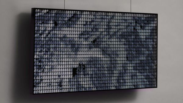
Behold Sea of Segments, an art piece by [Will Gallia] that really pushes what’s possible with seven-segment displays. The piece, which looks about the size of a decent flat-panel TV, is composed of an 8×6 array of PCBs, each of which holds an 8×4 array of white LED seven-segment displays; each board also holds two TLC5920 LED drivers. [Will] designed the PCBs to tile horizontally and vertically, making it possible to take data either from the top or right side and output to the bottom or left. Power is distributed to the modules through a series of steel bus bars, which also provide structural support for the display. The whole thing lives in an enclosure with a smoked acrylic front panel, and hangs from a pair of steel cables that also provide power.
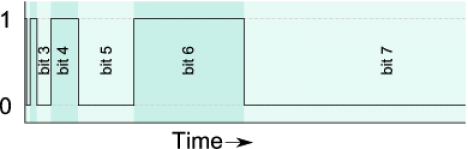
Under the hood, a PocketBeagle does all the heavy lifting of talking to the display and translating images onto the display. [Will] came up with an encoding scheme that gives about five bits of grayscale, and built a program to figure out which segments should be lit to create an image. The result is a smooth and convincing reproduction of videos of waves on a beach, which is where the project gets its name. Check out the results in the video below.
[Will] says he drew inspiration for this build from the DigitGrid by [Skot9000]. That was a great project too, but Sea of Segments takes the concept to another level.
Continue reading “Sailing On A Sea Of Seven-Segment Displays”