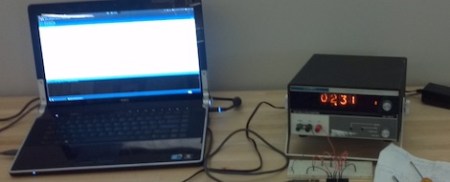
Surprisingly, up until a year ago, [Jimmy] hadn’t seen a Nixie tube. Awful we know, but he has come around to the beauty of glowing numbers in a tube. He recently found an old millivolt meter in a junk pile that used Nixie tubes. The wondrous orange glow beckoned him, so [Jimmy] decided to build a clock.
Just about all of the Nixie clocks we’ve seen (including non-clock builds) rely on building a controller for the Nixie tubes. The controllers range from Nixie Arduino shields to the good ‘ol 74141 IC. [Jimmy] realized he didn’t need to bother with controlling the tubes in an already functional millivolt meter – he only needed to send the right voltage.
For his clock build, [Jimmy] used an Arduino to output a voltage through a bunch of resistor dividers. For example, if the time is 12:30, the output voltage will be 12.30mV. Using this technique, the values for the needed resistors don’t exist, so a little bit of PWM means the Arduino keeps fairly good time.
There’s one added bonus of [Jimmy]’s clock – because the voltage varies around 0.01mV, the finished project acts like a digital version of Lord Vetinari’s clock. It may not be perfect, but at least a nice piece of equipment was saved from the trash.


Love it! Kudos to you Jimmy!
I have 5 nixie tubes in a drawer… One displays digits, the other four are symbols (probably math signs)… Aside from makeing them into eyes for some steam-punked robot, what should i do with them?
I would make something like a Simon game, a display chaser, or find a way to output something useful.
A steampunk Nixie Simon game would be pretty awesome come to think of it
If they are Soviet IN-15 tubes you can do this: https://sites.google.com/site/mjrippe/nixie-punk-display
I have a HP 3440A standing on my shelf, this is a great idea for an addon, so i can use it as a clock, i don’t use it anyway, since my HP 34401A is a tad bit more usable :-)
What is most funny is the model numbers are almost the same – a coincidental thing ?
http://www.messmuseum.de/hp3440a.htm
great idea man! this is a very smart hack.
Interesting way to generate the necessary voltage, PWM on a resistor ladder.
I would have tried a normal R-2R resistor ladder, without the PWM. You would need 12 output pins, but you could stick with resistors of a single value, and then scale it to a max voltage of 40.95mV. This way you could count in discrete steps of 0.01mV up.
I’ve seen a similar hack done to digital counters, where simply a pulse is sent to the counter once per second, 41 pulses each full minute and 4041 pulses each full hour. Gives a nice effect as the number runs up and then settles.
I actually thought about that, but I decided I wanted to minimize the pins used to both A) leave room for buttons for control, and B) use fewer pins in general for a smaller microcontroller that I could make a PCB for that just bolts on to the terminals.
damn widh i would have not gave away my ole heathkit freq unit !!