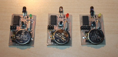
Here are the guts of [Lukasz’s] infrared camera remote control. He based it off of an existing design, but looked for places where improvements could be made. He felt the ATtiny2313 was a bit wasteful in this case. But further investigation led him to see why it was chosen. If you were to drop down to an ATtiny13 the ability to connect a crystal oscillator is lost (that chip only offers a 1-pin clock signal input) and the internal RC oscillator isn’t quite up to his standards for reliable IR communications.
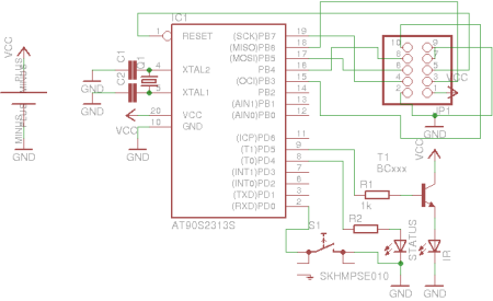
Instead of driving the IR LED directly from an AVR pin he used a transistor in hopes that it will allow the maximum current to flow through the diode when in use. We’re not sure if it’s necessary, but we can see how it makes sense. Power is received from an unregulated 3 volt coin cell, so maybe as that voltage drops over time this will come into play.
Speaking of that coin cell, battery life is a concern here. [Lukasz] is using the sleep functions of the AVR after three seconds of use. This should keep the cell alive for quite a long time. But his 0 volt measurement is an anomaly with the multimeter he’s using. To get a precise measurement for tiny current flow you need extra equipment, like [Dave Jones’] uCurrent adapter.
The schematic for this Canon camera compatible project is only provided in Eagle format so we’ve embedded an image of it after the break for your convenience. You should have no problem making this work with a Nikon if you swap out some of the code from the TV-B-Gone shutter release we saw on Thursday.


What is wrong with the internal calibrated RC oscillator of an ATTINY13? Its tolerance is about 2% from 0 to 40 deg C, normal use.
There are many designs using 8 pin chips that work just fine.
You can also use both the OC0A and OC0B as the same kind of PWM output, parallel them and get double the current.
Also, simply powering the circuit through the button can make your device consume zero current.
Yes I too would like to know what the issue was. I have a remote transmitter and receiver built from ATmega88 (I have many of these chips just lying around), and clocked at 1MHz they have no problem encoding a 32kHz carrier frequency needed for this, and the ATTiny13 has a 9.6MHz oscillator.
In fact thinking back to high school I used a ATTinysomething for a remote transmitter too.
Could this be down to issues with poor coding rather than issues with Oscillator itself? Not only is it accurate to a reasonable percentage as you say, but it can also be trimmed in softer for further accuracy if required.
Someone please enlighten me.
Factory calibration of the attiny13 (for example) is +/- 10%. It can be calibrated to +/- 2% with the right tools.
Lukasz mentions not having an oscilloscope to calibrate. There are other ways (AVR053), but he might not have had the right tools.
Putting a crystal on a bigger chip is an easy option, however I agree that using an attiny13 would be cleaner! Why not go even smaller and get an attiny4, it would do the job just fine.
Just noticed the way the transistor is connected. There is a limiting factor there. Move the LED in the collector of the transistor and ad a 10ohm resistor in series with it.
With the actual configuration: the LED requires close to 2V(at high current); plus 0.6 for VBE is 2.6V. The uC provides a 3V output getting a 0.4mA curent through the base resistor. Say a beta of 100, this gives you only 30mA through the led. So, change things like mentioned above. Look how it is done here: http://dicks.home.xs4all.nl/avr/nikon/index.html
Or just change the base resistor. The uC is capable of outputting much more current, so even if you wanted to put 300mA through the LED it would mean putting 3mA through the base which is perfectly within reach of the uC given 3-(2+0.6)/3mA=133ohm base resistor.
No need for circuit redesign. Although I agree the design is bad practice.
Thanks Bogdan & Garbz (and all others). Now I see it clearly (I drew your calculations on paper, and got the same results). Apparently I forgot that VCC is not 3V but 5V. So I replaced 1k resistor with 100ohm one, but unfortunately range of operation has not increased. I believe, that current through the IR diode should be about 400mA now, but apparently that was not the case.
Why this “transistor-as-a-switch” configuration I used is a bad practice? And why design proposed by Bogdan (as seen on this Nikon site) is better? Thanks guys!
Bogdan is right, the RC oscillator in the attiny13 is just fine for IR camera remotes (at least for Nikon DSLRs). I made an interval timer out of an attiny13 using the RC oscillator and it works great. The whole device (with enclosure) is barely bigger than the coin cell powering it.
For a remote like this, you can save a LOT of power if you use the button to control power to the circuit.
@FFFF00 you are right, the absolute value for the oscillator is within +/- 10%. It does vary within 2% between 0 and 40 deg C.
Still, i don’t think that the camera will reject the command if there is a 10% variation in pulse duration. The manufacturer might have thought of this in order to use a cheap RC oscillator in the remote rather than a crystal.
Anyway, trimming of the software may be done without an oscilloscope. A simple frequency meter is enough. But one might just change the software timing until the remote works. Once the working point is found, the oscillator may be considered stable enough for normal use.