Photogrammetry is the process of 3D scanning an object by taking a lot of photographs, then using software to turn those into a 3D model. But the process can only scan what the camera can see, and one can’t always get a good view of every part of an object. To solve this, [Thomas Megel] shared an experiment in using a mirror to capture the underside of an object simultaneously with its top. The results were encouraging!
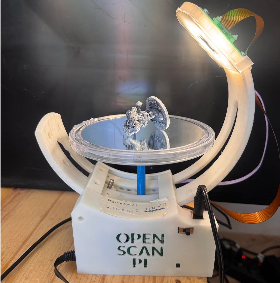
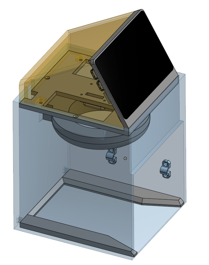
To do this he perched a small tabletop gaming mini on a mirror serving as a turntable platform in his self-designed OpenScan Mini machine, which is designed to take highly structured photos of small objects for scanning purposes. This produced a single scan with two objects, the original and its mirror image, together in one file.
Aligning separate models and combining them into one is a common way to deal with partial or incomplete scans. The idea here is to get two scans at once, instead of separately with a reposition of the object in between. Additionally, it should be possible for the software to automatically separate, align, and combine the two since it is known exactly where the mirror plane is.
As far as a proof of concept, it’s encouraging. [Thomas] is still playing with the idea and looking for suggestions, so if you have any insights be sure to share them.
3D scanning can be a very useful tool, and while photogrammetry can be done with little more than your mobile phone’s camera, in some ways the concept is over a hundred years old.