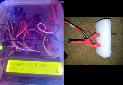
[Andy] is getting his garden up and running. This year it’s been pretty cold so he decided to get small plastic domed tunnel which acts as a mini greenhouse. To help monitor that environment he built this sensor array which displays temperature and soil moisture readings.
Temperature is quite simple. He’s using a TMP36 sensor which is held a few inches above the soil. The moisture sensor is of his own design. It uses two building screws embedded in foam. These are pushed into the soil and a resistance reading indicates moisture level. By driving voltage on one screw, and measuring voltage on the other he gets some useful data. It’s not a standardized value, but observation over time will let him know how the scale relates to dry or wet soil.
During the build process he found that he needed a pull-down resistor on the probe used to take the moisture measurement. He also uses an I/O pin to drive the other screw. This gives him a way to shut off the juice when not taking a reading. We just hope he’s either got a current limiting resistor, or is using a transistor to drive it high.


I would be a little bit worried about having your screws dissolve over time, or even simple oxidation skewing your results. Another option would be to dip the screws in wax or some other inert coating, then using capacitive sensing instead of resistive. Arduino has the ever useful capSense library that should make implementation a breeze.
I agree totally but using a capacitive reading would be really hard to calibrate.
Because soil composition would change the capacitance also.
I am sure there would be other variables that would effect the readings.
Yeas ago I remember a device that was being used by rain-bird a company that made lawn sprinkler systems.
A ceramic device that you put in the ground and was encased in some kind of mortar that you mixed and placed the sensor in the mortar 9 inches in the ground.
This approach will work, obviously, but I agree that capacitive sensing is definitely the way to go. To get around the issues with soil composition, you can use an approach similar to that of the sensor in mortar. All you need to do is contain the sensor within a stable medium that will also absorb water. You could use something like floral foam to encase the sensing elements.
in fact capacitive sensing is easier to calibrate as water is the biggest influencer of the dielectrum, whereas with the two spikes you are measuring resistence/conductivity, which is influenced much more by ions.
A combination of capacitive sensing and electric conductivity doesnt only give info on the moisture of the soil but also about having to add fertilizer or not
The Garduino (http://garduino.dirtnail.com/) is another “engineered gardening” project, and I think that they used probes made of stainless steel wire. As far as capacitance sensing of the ground moisture, I remember a proximity sensor alarm system that used two sensor circuits, one to measure the air capacitance, and the other to sense people/animals. They were set up in a bridge circuit. You might be able o calibrate it with an air reading and submerged in a bucket of water. I’m pretty sure you want to be somewhere in the middle.
I’ve experimented with capacitive sensing for hydroponics NFT using a Tiny2313. The sensor geometry is important, I used a coated PCB for this. There’s a circuit and code here:
http://krazatchu.ca/2010/05/20/capacitive-water-sensor/
interesting. Your probe -since it is flat- might not be influenced by soil humidity that much it seems (I am no expert) but I cab imagine it performs well in NFT
Hi folks,
Thanks for dropping me some feedback, on the oxidisation of the probes, I’m trying to offset this by only applying voltage to the circuit when I want to take a measurement, hopefully reducing the corrosion.
Thanks for the hint [John] on the capSense, will look into that.
By driving voltage on one screw, and measuring voltage on the other he gets some useful data.
That the hell does this mean?
his soil probes need to be longer unless all he cares about is the surface moisture.
If you are using resistive sensing, I would alternate which pin is sensing and which is driving. This way, you don’t build up material on the pins due to electrolytic reactions, because the process is reversed in each cycle.
The problem with measuring the impedance (resistance) of the soil and drawing conclusions on the soil moisture is that, as soon as you add any additive (fertilizer) to the water, it will ruin any previous calibration.
What you need is to have “something” that does reflect relative moisture, but does not get affected much by changes in chemical composition of the soil.
One possible (and cheap) approach is to have your electrodes in the cylinder made of plaster of Paris (gypsum) – it perfectly absorbs the moisture, and due to it’s chemical composition it won’t change electrical properties (conductivity) due to changes in the soil’s composition.
You still need to do the initial calibration, but once done, you don;t have to think about it anymore.
it is prohibitively expensive to drill wells and take samples from the depths that would be involved in carbon sequestration, so research often relies heavily on mathematical models. Li uses a combination of numerical simulations and experimental work that aims to mimic relevant underground conditions. She and her team, composed of a few graduate students and post doctoral scholars, split their time between experimental work and numerical simulation to better understand the subsurface complexities associated with geologic carbon sequestration.