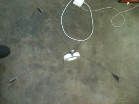
With the Olympics on there are a lot of really great camera shots shown during the events. One of the best is the overhead view, which is provided by a camera suspended between cables. It’s not new for the Olympics, SkyCam has been around for over twenty years. What is new is [Dan Royer’s] attempts to build his own aerial camera setup.
He’s not starting from zero with this project. [Dan] has done some really great work with the Drawbot. It’s a two-motor, two-axis plotter which uses CNC to draw on a white board. For this project he combined two Drawbots in order to add a third axis. The image above shows the camera mount suspended between the four strings. He’s been working hard on getting the software ready for this kind of addressing. Along the way he broke the strings a few times because he was too far from the kill switch to stop it in time. But what he’s got is a nice start and we hope to see a more illustrative follow-up soon.
One of the things that SkyCam has going for it is a stabilization system. We wonder if a spinning gyroscope would work as well as it did for that balancing bike.


http://www.youtube.com/watch?v=JCWgiaVhHXM
video of it in action. Thank you!
What are you talking about when you say “Here’s Tokyo, and here’s Berlin”? Is this somehow being done remotely as well?
Thank you, and good question!
Tokyo and Berlin are the names of the two drawbots. Look at the image titles and descriptions on the original blog post for an explanation of almost every part.
Dan do you have any workable prototype for your skycam field?
The biggest part of skycam or what is actually called spidercam is that it has variable speed clutches to go from 0.001mph to 50mph and back very smoothly. steppers will not do that.
He needs to look at constant spinning motors and clutches with brakes.
industrial servos should allow that, as they have speed feedback and are designed to handle incredible accel/decel rates.
Interesting ideas! At the scale I’m working I don’t need either solution. I’ll make a note for the day when someone says “make it again, only…. huge.”
Wonder if some small CVTs would work?
today is that day…will you make it again, only…huge? I have a plan for something like this in a theatre to move around an orb of light for a high school play… Any interest?
Like http://www.youtube.com/watch?v=W0BERPIp364
From what I know, the SkyCam does not have a gyro. the mount and the control system makes the camera stable. the cables mount to the corners of a square on the mount. each corner can move a little thanks to a ball joint. the control software has a Deceleration in it to make nice smooth stops. Also spidercam is a DIFFERENT. SpiderCam is on a single cable path and moves along that. Best example is X-Men 3 when wolverine is thrown through the trees. Spider cam is how the followed him.
It has 2 gyros actually I read when googling
Nice! I always considered using one of those X/Y marker plotters for a macro-level SkyCam.
Seems the original uses a rectangle with bars sticking from the corners where it’s attached to cables on the end, and the attachment points are up and down rotating things I gather (the only up and down nature might be significant), and of course it has a part with the camera sticking out below the rectangle and some other stuff (including gyros) sticking out above, but even omitting the gyros I think that does a lot for stability.
Random image search result: http://www.instablogsimages.com/images/2006/02/21/flycamear.jpg
From that picture it also seems to have the central column be of the old steadycam leveler design, for which HaD has some nice home-made examples.
I believe there’s a kind of universal joint in the center and on top is a battery, radio, gyroscope, and camera drivers.
I think though that the weight distribution must follow a rule, and you can’t have a light camera on the bottom and tons of weight on the top I imagine, so if you make your own version you night not be able to put the same stuff on top. Unless you add ballast to the bottom I guess.
the top of the camera is the transmitter and receiver unit. and sensors. the camera has sensors to prevent collisions ie goal post.
the camera control and its feed are wireless.
iv’e been wanting to do this for 4 years now.. I asked a robotics professor about stabilizing the robot using kinematics and feedback loops, he said , and I quote, “it can be proven that this system has an analytical control solution. care for a masters project?”
Wait – I can get a masters thesis for a robot I already built? Free degree?!? Where do I sign up?