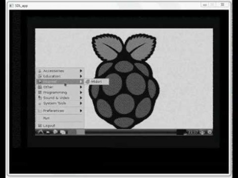
Confronted with a monitor that would display neither HDMI signal, nor composite video, [Joonas Pihlajamaa] took on a rather unorthodox task of getting his oscilloscope to work as a composite video adapter. He’s using a PicoScope 2204 but any hardware that connects to a computer and has a C API should work. The trick is in how his code uses the API to interpret the signal.
The first thing to do is make sure the voltage levels used in the composite signal are within the tolerances of your scope. [Joonas] used his multimeter to measure the center pole of the RCA connector and found that the Raspberry Pi board puts out from 200 mV to 2V, well within the PicoScope’s specs. Next he started to analyze the signal. The horizontal sync is easy to find, and he ignored the color information — opting for a monochrome output to ease the coding process. The next big piece of the puzzle is to ascertain the vertical sync so that he knows where each frame starts. He got it working and made one last improvement to handle interlacing.
The proof of concept video after the break shows off the he did. It’s a bit fuzzy but that’s how composite video looks normally.


deserves props for that, nicely done. I’d hate to use it myself, but still, i like the hack.
Wow, good to know – the important thing here is that the PicoScope supports continuous streaming mode. Most scopes (even your nice benchtop ones) are not capable of continuous data capture or streaming – they typically capture bursts of samples when triggered. This makes the PicoScope also useful as a DAQ of sorts.
(Correct me if i am wrong, but) I dont think composite video is “normally fuzzy”… pixel stretching and jittering syncs will make a video signal “fuzzy.”
The fuzziness is actually the colour signal which is modulating a higher-frequency carrier. For a greyscale output like this the signal should be low-pass filtered to remove it.
Very interesting hack!
I expected another “watch video on your oscilloscope” hack with an oscilloscope in X-Y mode connected to a couple of sawtooth generators, and the Z input connected to the Raspi.
So the movie made no sense: no oscilloscope would produce a picture like that.
Then I went to the page and saw that what he’s essentially doing is using the A/D converter from a software scope and decoding the NTSC signal in software.
A software-defined video decoder! Love it!
I’m eager to see if color is possible, but at 6.67MS/s I think it won’t be: the sample frequency is probably not high enough.
Yes, the chrominance information is modulated at 3.6-4.4 MHz and sine wave phase & amplitude is used, so any decoding of individual pixel (at over 5 MHz) chrominance would require at least 10x the amount of samples (maybe more), so something like 100 MHz sampling rate would be preferred. As the data would be hard to compress, it would likely require USB 3.0 bandwith to do.
But, with a composite signal decoding circuit that would have analogue oscillators and other components to separate color, a 3-channel scope might just be able to do it, although USB2 bandwith might still be a issue. :)
Your numbers are correct for PAL, but overly generous for NTSC; the chroma component goes up to 3.6+1.5MHz = 5.1MHz. Audio (in OTA format) is modulated at 4.5MHz, but won’t be present here.
The canonical way to decode NTSC is (BT.601), which uses a 13.5 MHz sample rate.
Sampling at anything over the Nyquist frequency would be adequate, assuming a low enough noise floor.
Ah, it may just be my lack of digital signal decoding knowledge then; I assumed that detecting phase modulation of 5 MHz sine wave digitally would require a sampling rate much exceeding the Nyquist frequency.
However, I’d still prefer a sampling rate in excess of 15 MHz if I were to try adding color support to my decoder project. Dedicated analog components that are designed for the application have the necessary characteristics “built in” have some tolerance to noise, but with digital signal some headroom would be preferred. :)
Very nicely done.