Many projects on these pages do clever things with video. Whether it’s digital or analogue, it’s certain our community can push a humble microcontroller to the limit of its capability. But sometimes the terminology is a little casually applied, and in particular with video there’s an obvious example. We say “PAL”, or “NTSC” to refer to any composite video signal, and perhaps it’s time to delve beyond that into the colour systems those letters convey.
Know Your Sub-carriers From Your Sync Pulses
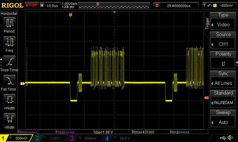
A video system of the type we’re used to is dot-sequential. It splits an image into pixels and transmits them sequentially, pixel by pixel and line by line. This is the same for an analogue video system as it is for many digital bitmap formats. In the case of a fully analogue TV system there is no individual pixel counting, instead the camera scans across each line in a continuous movement to generate an analogue waveform representing the intensity of light. If you add in a synchronisation pulse at the end of each line and another at the end of each frame you have a video signal.
But crucially it’s not a composite video signal, because it contains only luminance information. It’s a black-and-white image. The first broadcast TV systems as for example the British 405 line and American 525 line systems worked in exactly this way, with the addition of a separate carrier for their accompanying sound. Continue reading “How Do PAL And NTSC Really Work?”