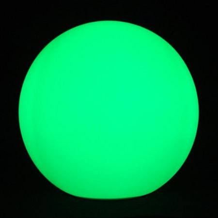
Knowing that I’m always happy to get something new and glowy, my wife brought home a cheap “floating pool light” that she found on sale for roughly $10. This is a large white floating ball that has LEDs inside and cycles through different colors. Meant to be put into a pool for neat effects, we found it to be much more interesting just used around the house.
However, it was a bit too bright and cycled colors too quickly for our taste. It was actually somewhat distracting when we were just trying to sit and have a few beers late at night on our patio. This gave me a perfect excuse to tear it apart and start hacking… like I wasn’t going to do that anyway.
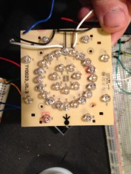
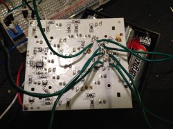
What I found inside was extremely simple. There’s a single un-marked chip that holds the different display modes (there were 3 display modes: warm, cool, and white). The LEDs were arranged in an array of Reds, Blues, Greens, and Whites (half marked yellow).
My goal was to make this a little more tolerable as mood lighting, so I needed to draw up a plan. I have an arduino sitting here from the redbull contest, so I figured why not hook it up to that? It would allow full PWM control of the channels and I could do some pre-programmed sequences if I wanted.
This was ridiculously easy. All I needed to do was solder leads on to each of the LED channels. There are already great tutorials on how to run PWM from the arduino and a couple quick additions would give me direct controls over each channel via potentiometers. So problem solved right?
Well, sort of. It really bugs me that there’s an entire arduino there just for some PWM. I can go buy the components to do 555 timer PWM circuits if all I want is PWM. Then again, if I compare the price, that free arduino is a much cheaper solution than buying 2xcaps, 1×555, 1xtransistor, and assorted resistors and diodes, especially if consider that I’d have to buy it all in triplicate.
Ultimately if I wanted to just leave this as PWM control on each channel, I’d opt for the 555 circuit. What else is there to do with a glowing ball? Simple notification system? Sound reactive? Give me some ideas.





Why dont you use ATTiny85?
extremely small and cheap, and has 2 PWM.
actually works with an atiny13 too. I built this. didnt use hardware pwm because i wanted the code to be the same for all 3 pins
http://www.youtube.com/watch?v=1xEAsQIgzqk&list=UU_Q9h1wxo57Pn1O0bOCzVdw&index=4&feature=plcp
well shit wrong link and i dont see an edit
http://www.youtube.com/watch?v=1xEAsQIgzqk
good suggestion. since what you have is rgbw, 2 channels might be more than enough if you accept that you can’t make every possible color. just use 4 of the available digital i/o pins to turn on/off a set of mosfets, selecting two of the 4 available colors. if the pwm duty cycle of two colors is identical, with some design consideration, you could opt to run two colors off of one pwm channel to expand the range of colors at the expense of buying more mosfets.
The attiny25/45/85 actually has 3 pwm channels, so, yes, it works very well for RGB LED configurations.
Put an acclerometer in there and let the Arduino sample it. You could try and have the accelerometer distinguish between a splashdown and a bounce. On a splashdown the ball turns blue, on a bounce it turns red or something. I think your idea about the notification system would also be cool.
Good one Caleb! I’m a bit fan of glowy light-things, so I might have to try something like that.
The unmarked chip is certainly a microcontroller, either a pic or avr, you could have just reprogrammed it.
theres more to life then AVR and PIC, in fact, i bet 50 bucks it is NOT AVR or PIC
it will be some microcontroller (uC) that youve never heard of…
there are litterally HUNDREDS of microcontrollers around, AVR and PIC is only a *_small_* assortment of whats available!
Well, +1 this
not only is this true, but many are burnt so that you can’t reprogram them. The time it would have taken to sniff this and try to figure out would have been longer than it took me to simply interface with the arduino/555 timer.
You don’t need a uC to blink a few LEDs.
There’s heaps of PWM chips. Got a cordless drill? It probably uses a PWM chip called G1??? (I can’t remember), I didn’t find a datasheet but did find a seller (MOQ 10,000!).
You can get RGB LEDs with the PWM chip built in, see http://www.dansdata.com/gz065.htm. Check the date – 2006!
You can’t just stuff a dozen of them into the ball though, they’ll run out of sync. Maybe just one will be bright enough, current ones claim 5000mCd. Not much of a hack though.
Make it remote control ala Blue Man Group and have your wife get a few more.
Temperature monitor, since it’s in the water!
I like this idea, have the color set to blue for a temperature that is too cold for your taste and gradually goto red for what you prefer.
If you really want something neat, also add a ballast tank, like a submarine. Have the ball sink to specific depth based on temperature as well, or proximity.
Make it in to an alarm clock, maybe stick a
bluetooth on it and let your phone do the rest
Well Phoey, when he said “large” I was thinking something like 20″
was thinking that a few just loose in the yard might be nifty on occasion.
Just curious, how would you figure out what microcontroller that was, if it has indeed been scrubbed clean, also would it be possible if it had an external clock to just use a clock of a lower frequency to slow it down?
good idea, why havent i thought of that? will try it soon! :)
I didn’t figure it out. I bypassed it and used an arduino or a 555
Sound reactive would be cool only because i’m a noob and would love to make one.
Well, you could program it with less predictable patterns that would make it much more interesting.
finally got an idea worth mentioning.. yet still simple
1) get a few more ;)
2) have it randomly choose a color at powerup (battery insertion)
3) have it turn off LEDs during the day (auto)
4) have it change to next color when light turns on at sunset
5) color of individual ball can be changed (to next) from far away using bright flashlight or even bright IR flashlight or even (IR) laser if desired
6) sweep the yard with your (IR)flashlight/(IR)laser for stunning effects XD
and noone mentioned SOLAR !!!!?!??????!?!?!?
so there, make it solar along with what i just said, would make for a years long entertainment-mood lighting. maybe even add a manual-white switch for regular light
You’ve not seen the RGB garden stake lights then?
Meassure watertemperature and sent wireless? :)
First, make it wireless.
Second, add sensors. Light sensors, temperature sensor, gyro/accelerometer, and see if you can electrically measure the PH or chlorine in your pool.
While idle, it can cycle through colors, etc. But connect to it and it will change to a color corresponding to either the small movements/waves in the pool. or just scroll through colors. when connected, you can have it display a color corresponding to the sensors like water temp, or PH level.
Make it self-propelled.
(Actuator so it can make itself off balance in arbitrary direction and ball for it to rotate in, so it will roll around if placed on floor).
Sensor so can confine its ramblings to an area (e.g. with a RF emitting wire for a fence).
So it can gradually wander around within a user defined area – without actually having a pond.
For this particular equipment, I’d rig a wireless RF remote for mode switching, a rechargeable power cell, a solar cell, and fill the chamber with helium, and let it go. :)
curious to know where you ended up. I also saw these balls on amazon and picked a few up because I thought they could make cool notifiers of some sort. They arrived today and I am wondering what you ended up doing, and what, if anything, you’d be able to share.
i just set mine to cycle MUCH SLOWER than it was originally. I used a meter of RGB LED strip that I had lying around. It was neat for a while, but it became parts eventually.
You don’t still have the arduino code you used for the slower cycling, do you?
I think my last comment was eaten…..anyhow, I’m wondering if you will be adding an RF link. I’ve been working on a wireless RGB light controller using a WiFly module. The control/music sequencer software does most of the heavy lifting, and it will soon be open-sourced (the hardware design is already released). It would be great to support more than one type of hardware implementation and these LED spheres seem to be a good fit.
Following up on that last message, I’ve released the source code for the light controller software. It’s still very rough around the edges, but it keeps getting better every day. Here’s a video clip of it in action: http://www.youtube.com/watch?v=wldjKPBRziA
Do you know BlinkM, FreeM and others ? (http://thingm.com/products/blinkm-maxm.html)
Did you have a Twitter account ? If so, relate the ball to. You will be aware…