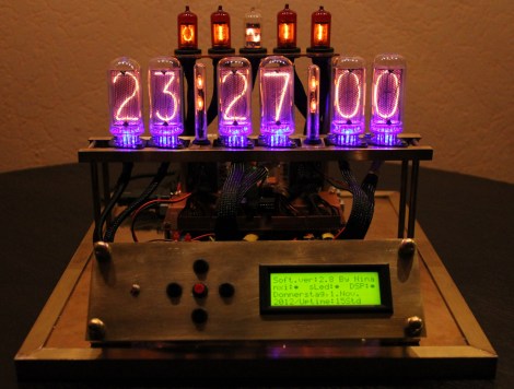
[Nina Blum] figures that if you’re going to the trouble of driving Nixie tubes you might as well use a lot of them. The details about this clock, which were sent directly to our tips line, lists a total of thirteen tubes used. There are six Russian IN-8 tubes (large digits), four Z573M tubes (small digits), but the colon tubes and the sine wave tube part numbers were not specified.
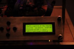
An ATmega8 controls the segments via a set of transistors. To operate the display [Nina] included a user interface made from five buttons and a four line character LCD. There is a video showing off the menu system that includes a way to set the time, date, and toggle the various illuminated bits. We’re waiting for permission to post that clip on our YouTube channel as [Nina] only included a Rapidshare link to the movie. Right now you’ll find more images after the break and we’ll embed the video if we get to okay.

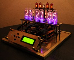
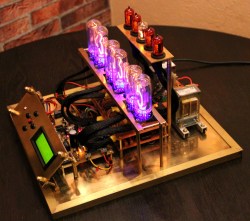
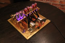
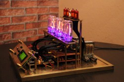


The colon tubes look like test tubes with neon bulbs inside.
Most likely correct. The Sine wave is probably a Z5710M.
I’m sorry but the green LCD detracts from the whole ensemble for me.
Yah a VFD would have been more fitting.
agreed.
I know I’m late to the party, but: 5″ CRT with stroke-drawn characters. These were being used in some programmable calculators in the same era as Nixies.
Or a series of chicken-head knobs mounted on a battered oak panel…
I disagree with you all, I think the LCD and modern construction makes it better.
It makes it look like something special from a recent time rather than something average from the old times.
the LEDs under the tubes always bother me
Looks cool, but if it were mine, I would have the whole thing under smoked glass where only the numbers we seen. Then open it up to show the tubes, or have some back lighting that shows of the tubes and circuitry. Having the LCD in view would be a distant 3rd. Although a VFD would move it up the list some.
Its nice to at least see the pictures but a build log would be great and a video that could be played on a g5 ppc.
I love it :) Thanks for an interesting looking build.
DIE RAPIDSHARE DIE!
I know, the large tubes are not IN-8 as those have not a flat top. I think they really are IN-18.
The setup reminds me a lot of the “Blue Dream Nixie Clock” from Nocrotec.com (Dieter Waechter) and clausurbach.de, also the reference to the ATMega. They do use IN-18 and the colon tubes are self made ones.
Am I the only one who fears for the micro’s safety if it’s directly driving the transistors? If one of them fails short, it’ll probably blow up the micro (though it’s not a big deal with a cheap device, especially if it’s socketed).
My own slowly-progressing Nixie project uses Darlington optocouplers to ensure everything stays safe.
Very nice build, but I would have gone the extra mile and made a “steampunk” style case for it :P
First I have to say overall I like the build, it looks clean and neat. However, I must agree with others here who pointed out the LCD just doesn’t go with the rest of the project. It should either be hidden away, or replaced with a VFD. I think nixi tubes are cool, but I don’t really care for mixing different era’s of technology like that.
Nice! I like the way its innards are exposed. Looks quite steampunk to me ;-)
The big numbers are definitely IN-18, and I’m pretty sure the colons are made with neon bulbs inside test tubes.
Software must have been fun to get together!
As a matter of personal taste, I am happy that you can turn off that green LCD… Green is evil…
Are those two transformers back to back to form an isolation transformer? Heavy and bulky, but simple. Why bother with a buck-boost converter at all indeed? Hmmmm, got me thinking…
On the topic of nixie tubes; anyone know the best places to get them? Does ebay tend to be a ripoff?
Just a thought, I did a test today
with one of those HV850 chips and
a rectifier, am getting 75V DC
which works well for VFDs and
probably some smaller nixies as well.
Display should have been VFD… but would have IDEALLY been panaplex or a neon plasma display (like what they used in old pinball machines)