RF Remote Made Easy

The 433 MHz spectrum is a little bit of an oddball. It’s one of the few areas of the radio spectrum which is nearly universally unlicensed Outside of the US, it’s an open playground for devices that adhere to the power restrictions and other guidelines about best practices. IoT devices operate here, as well as security systems and, of course, remote controls. And, using a few off-the-shelf parts [hesam.moshiri] shows us how to take advantage of this piece of spectrum by designing and building a programmable and versatile 4-channel 433 MHz remote control.

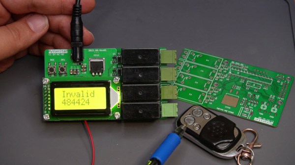
Built around an ATmega8 microcontroller, making it easy to work with Arduino sketches, and with a 2×8 character LCD for ease-of-use when not connected to a computer, the wireless switching device can store up to 80 remote control codes in its EEPROM memory. This was one of the harder parts for [hesam] to sort out, but using structures to store the data for the codes eventually solved the problems. A simple GUI makes using it with whatever remote happens to be on hand fairly straightforward, including the ability to record codes from existing remotes on the fly and also to associate those codes with specific actions.

Schematics and a bill of materials are available on the project’s page, making this fairly accessible to those looking to add some wireless connectivity to a project, home automation system, or IoT device. It’s mainly set up as a switching device, but with some modifications could be put to work doing more complex tasks. The 433 MHz spectrum is an exciting place to be, too, and things like setting up entire security systems using it are not too far removed from a switching device like this.

[Editor’s note: As many mentioned in the comments, 433 MHz is a licensed ham band in the USA (ITU Region 2), so you can’t use it without a license. (Get one, it’s easy.)  In the USA, the equivalent band is at 315 MHz, which is why garage door remotes usually come with a 315/433 choice. Either way, check your local laws before you transmit.]

Continue reading “RF Remote Made Easy”

A Simple Serial Display

Often with more “modern” complex protocols involving handshaking, token exchanges, and all the other hoops and whistles accompanying them, we forget how useful and powerful serial can be. In what might be a wonderful tribute to that, [Davide Gironi] created a simple AVR-powered 16-digit serial display.

It can display two numbers, and that’s it. A MAX7219 drives the display, and the brains are an ATmega8. It’s straightforward to send new values: a start byte, a CRC, the data to display, and an end byte. A CP2102 provides a UART to USB interface to connect to a host. An EEPROM helps it remember the last numbers shown. It supports positive, negative, and floating-point numbers.

This is a beautiful example of doing one thing and doing it well. The design is simple and allows it to be used for anything. You can show the current stock market price, the time for the next two trains for your commute, or whatever else you can think of. [Davide] included a schematic, code, and a 3d printed enclosure.

Perhaps the idea could be combined with a clever design for a single-motor seven-segment display.

Continue reading “A Simple Serial Display”

The Not Quite USB-C Of Nintendo Switch Accessories

Historically gaming consoles are sold at little-to-no profit in order to entice customers with a low up-front price. The real profits roll in afterwards from sales of games and accessories. Seeking a slice of the latter, aftermarket accessory makers jump in with reverse-engineered compatible products at varying levels of “compatible”.

When the Nintendo Switch was released with a standard USB-C port for accessories, we had hoped those days of hit-or-miss reverse engineering were over, but reality fell short. Redditor [VECTORDRIVER] summarized a few parts of this story where Nintendo deviated from spec, and accessory makers still got things wrong.

Officially, Nintendo declared the Switch USB-C compliant. But as we’ve recently covered, USB-C is a big and complicated beast. Determined to find the root of their issues, confused consumers banded together on the internet to gather anecdotal evidence and speculate. One theory is that Nintendo’s official dock deviated from official USB-C dimensions in pursuit of a specific tactile feel; namely reducing tolerance on proper USB-C pin alignment and compensating with an internal mechanism. With Nintendo playing fast and loose with the specs, it makes developing properly functioning aftermarket accessories all the more difficult.

But that’s not the only way a company can slip up with their aftermarket dock. A teardown revealed Nyko didn’t use a dedicated chip to manage USB power delivery, choosing instead to implement it in software running on ATmega8. We can speculate on why (parts cost? time to market?) but more importantly we can read the actual voltage on its output pins which are too high. Every use becomes a risky game of “will this Switch tolerate above-spec voltage today?” We expect that as USB-C becomes more common, it would soon be cheapest and easiest to use a dedicated chip, eliminating the work of an independent implementation and risk of doing it wrong.

These are fairly typical early teething problems for a new complex technology on their road to ubiquity. Early USB keyboard and mice didn’t always work, and certain combination of early PCI-Express cards and motherboards caused damage. Hopefully USB-C problems — and memories of them — will fade in time as well.

[via Ars Technica]

[Main image source: iFixit Nintendo Switch Teardown]

A Simple Programmable Light Controller

Everything’s internet connected these days, garage doors, baby monitors, and the kitchen sink are all hooked up. There are benefits to having everything online, but also several pitfalls. Maintaining security on a home network is an ongoing job, made more difficult by the number of devices that must be kept track of. Sometimes all the hassle isn’t worth it, and you just want a non-connected solution. [Dilshan] found himself in just that camp, and built a simple programmable light controller that doesn’t connect to the Internet. 

At the core of the project is an ATMEGA8 microcontroller, which is cheap, readily available, and can do the job. It’s combined with a DS1307 real time clock IC to keep track of time. The circuit is designed for 24V power, to allow it to be run from the same supply as the LED light modules it is designed to control.

The design was initially prototyped with through-hole parts on the breadboard, with the final design being built with surface mount parts on a custom PCB. Light is courtesy of a 7W warm white LED module. 3 push buttons and a 4-digit, 7-segment display act as the user interface, with an LDR to allow the light to also react to its surroundings.

It’s a build that goes against current trends, lacking WiFi connectivity, Twitter functionality, or cloud-based logging. It goes to show that the right solution isn’t always putting everything online. Sometimes the old methods are enough to do the job, and do it well.

Of course, if you’re still itching for a packet data fix, here’s how to blink an LED over the Internet.

Skeletal Robot Skips The Chassis

With the high availability of low-cost modular electronic components, building your own little robot buddy is easier and more affordable than ever. But while the electronics might be dirt cheap thanks to the economies of scale, modular robot chassis can be surprisingly expensive. If you’ve got a 3D printer you can always make a chassis that way, but what if you’re looking for something a bit more artisanal?

For his entry into the Circuit Sculpture Contest, [Robson Couto] has built a simple robot which dumps the traditional chassis for a frame made out of bent and soldered copper wire. Not only does this happen to look really cool in a Steampunk kind of way, it’s also a very cheap way of knocking together a basic bot with just the parts you have on hand. Not exactly a heavy-duty chassis, to be sure, but certainly robust enough to rove around your workbench.

The dual servos constrained within the wire frame have been modified for continuous rotation, which combined with the narrow track should make for a fairly maneuverable little bot. [Robson] equipped his servos with copper wheels built in the same style of the frame, which likely isn’t great for traction but really does help sell the overall look. If you aren’t planning on entering your creation into a contest that focuses on unique construction, we’d suggest some more traditional wheels for best results.

The brains of this bot are provided by an ATmega8 with external 16MHz crystal tacked onto the pins. There’s also a ultrasonic sensor board mounted to the servos which eventually will give this little fellow the ability to avoid obstacles. Of course, it doesn’t take a robotics expert to realize there’s currently no onboard power supply in the design. We’d love to say that he’s planning on using the copper loops of the frame to power the thing via induction, but we imagine [Robson] is still fiddling around with the best way to get juice into his wireframe creation before the Contest deadline.

Speaking of which, there’s still plenty of time to get your own Circuit Sculpture creation submitted. If it’s a functional device that isn’t scared to show off the goods, we’re interested in seeing it. Just document the project on Hackaday.io and submit it to the contest before the January 8th, 2019 deadline.

CNC Upgrade To Guitar Pickup Winding Machine

The idea of winding inductive guitar pickups by hand is almost unthinkable. It uses extremely thin wire and is a repetitive, laborious process that nevertheless requires a certain amount of precision. It’s a prime candidate for automation, and while [Davide Gironi] did exactly that, he wasn’t entirely satisfied with his earlier version. He now has a new CNC version that is more full-featured and uses an ATMega8 microcontroller.

[Davide Gironi]’s previous version took care of winding and counting the number of turns, but it was still an assisted manual system that relied on a human operator. The new upgrade includes a number of features necessary to more fully automate the process, such as a wire tensioner, a wire guide and traverse mechanism (made from parts salvaged from a broken scanner), and an automatic stop for when the correct number of turns has been reached.

guitar_pickup_winding_sample_microscope

All kinds of small but significant details are covered in the build, such as using plastic and felt for anything that handles the wire — the extremely fine wire is insulated with a very thin coating and care must be taken to not scratch it off. Also, there is the need to compute how far the traverse mechanism must move the wire guide in order to place the new wire next to the previously-laid turn (taking into account the winding speed, which may be changing), and doing this smoothly so that the system does not need to speed up and slow down for every layer of winding.

This system is still programmed by hand using buttons and an LCD, but [Davide Gironi] says that the next version will use the UART in order to allow communication with (and configuration by) computer – opening the door to easy handling of multiple winding patterns. You can see video of the current version in action, below.

Continue reading “CNC Upgrade To Guitar Pickup Winding Machine”

Hackaday Links: November 8, 2015

[Burt Rutan] is someone who needs no introduction. Apparently, he likes the look of the Icon A5 and is working on his own version.

Earlier this week, the US Air Force lost a few satellites a minute after launch from Barking Sands in Hawaii. This was the first launch of the three stage, solid fueled SPARK rocket, although earlier versions were used to launch nuclear warheads into space. There are some great Army videos for these nuclear explosions in space, by the way.

[Alexandre] is working on an Arduino compatible board that has an integrated GSM module and WiFi chip. It’s called the Red Dragon, and that means he needs some really good board art. The finished product looks good in Eagle, and something we can’t wait to see back from the board house.

The Chippocolypse! Or however you spell it! TI is declaring a lot of chips EOL, and although this includes a lot of op-amps and other analog ephemera (PDF), the hi-fi community is reeling and a lot of people are stocking up on their favorite amplifiers.

[Jeremy] got tired of plugging jumper wires into a breadboard when programming his ATMega8 (including the ‘168 and ‘328) microcontrollers. The solution? A breadboard backpack that fits right over the IC. All the files are available, and the PCB can be found on Upverter.

In case you haven’t heard, we’re having a Super Conference in San Francisco later this week. Adafruit was kind enough to plug our plug for the con on Ask an Engineer last week.