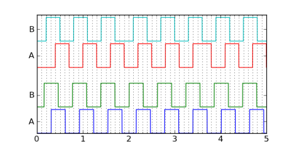
 Many motors offer a quadrature encoder that give feedback on whether, and in which direction, the motor shaft is moving. But if you’re clever about analyzing the data you can use a quadrature encoder to estimate motor velocity. [Jason Sachs] makes the case that it’s fairly easy to get this wrong. Lucky for us he has carefully laid out his process of extrapolating velocity from the two edge-trigger data sources.
The process starts with reading from the encoder. Many chips have peripherals that will interface with a rotary encoder, but hardware lacking that built-in helper can still be used by monitoring pin-change interrupts. Once connected samples are taken over time and the rest is left to the quality of your algorithm.
What can this velocity data be used for? That’s up to you. But we can think of a couple of projects. It may be useful in a spinning POV display like this FPGA-based beauty. You also find quadrature encoders in exercise equipment. Knowing the velocity will help if you’re building your own computer to replace what came with that Stairmaster.
[via Reddit]


“What can this velocity data be used for?”
Intelligent interfacing to rotary encoders: turn slow = increment/decrement by 1, turn fast = do it by 10.
etc.
“pin-change interrupts”
a.k.a. interrupts
There are other kinds of interrupts.
Without reading the article but knowing basic physics…
Velocity is the change in position divided by the change in time aka v=dp/dt.
For quadrature/rotary encoder you can either (a) time between the pulses or (b) count the pulses. With (a) you are measuring dt for a given dp (360/resolution), with (b) you are measuring dp for a given dt (timer period, or 1/timer freq).
For absolute encoders (grey or analog), setup a timer for a given period (dt), record the position (p1) and the previous position (p2), dp = p1 – p2.
The article discusses quadrature encoders. It’s worth reading, by the way. It does indeed discuss the two approaches you mentioned, but it goes into more depth about the tradeoffs involved with each.
This blog entry describes error sources and their magnitudes when working with rotary encoders. If you’ve worked with encoders, nothing here will be new.
No methods for dealing with these errors are presented – wait for Part 2.
I have a Tempest arcade machine. It uses quadrature encoding to monitor the position of the spinners, with hardware decoders. Since the relatively slow CPU polls the decoder circuitry, it’s possible to spin the spinner so fast, the claw moves backward around the pipe.
I wrote several comments on the blog, but somehow they’re not showing up, or being removed by the author (perhaps because he wants to cover the same method in part 2?)
What I’ve done in the past is recording the number of pulses (or steps up/down), and the timestamp of the last event. The control loop would keep a copy of these values from the previous iteration, and calculate both the delta position and the delta time. It can do this, because it has recorded the timestamps of the last event of this cycle, and the last event of the previous cycle; therefor, the delta time always exactly covers the time between the counted events. So you calculate the delta position / delta time, where neither is constant, and the two are always consistent.
If the time since the last recorded event is longer than the time between the two previous events, the speed is dropping; calculating the time since the last recorded event will give you an upper limit of the current speed, so when no more events are received (encoder stopped), the speed will asymptotically go towards 0.
Would you mind sharing some pseudo-code for your algorithm? I do not understand how the two timestamps are helping.
In other literature this is called the “Time Stamping Algorithm”. Depending on how it’s implemented, it is essentially a revised version of the Constant Delta-P Approach discussed in the article. In both methods an “event” is typically an interrupt from the quadrature hardware. So a timestamp will (almost) always indicate a single encoder tick (hence the name Constant Delta-P).
Though both methods have the same pros and cons, what’s great about the Time Stamping Algorithm you described is that it fixes a potential bug! It’s possible that, at high speeds or slow clocks, the internal quadrature register increments multiple times before the interrupt is processed. So it’s important to actually check how much the position has changed between Events instead of trusting that delta-P=1.
Umm. since velocity is a vector quantity, most rotary motors have zero velocity, even when they’re running. You could chuck it at your local mechanics nerd and give it velocity. ITYM “angular velocity” or “speed(rpm)”