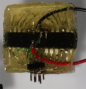
This is the back side of [Dmitry Grinberg’s] 8×8 LED matrix pendant. He had seen the other projects that used a 5×7 grid but wasn’t really satisfied with the figures that can be drawn in that confined area when each pixel has only the option of being on or off. His offering increases the drawing area and includes the ability to display each pixel at several different levels.
He’s using an ATmega328 microcontroller soldered directly to the pins on the back of the LED module. He mapped out the IO in his firmware to make the soldering as easy as possible. To protect the hardware he fashioned a mold around the edges of the LED package using duct tape. The tape held epoxy in place as it hardened, encasing the microcontroller and holding the power wires and ICSP header tightly.
After the break you can see about six seconds of the device in action. The four levels of brightness for each pixel really do make quite a difference!


Nice job!
Best. Video. Ever.
The video definitely miss some shaking too
Reddit-ready with the inclusion of a cat.
TERRIBLE VIDEO!
The video demos the cat walking behind him better than the pendant..
If you see how ugly the thing is, then see how the video hid that fact, I’d say it’s a pretty good video if you think about it.
TERRIBLE COMMENT
no decoupling caps! grrrr
Yeah, i made a bunch of AVR boards and once i forgot the decoupling on a low power board that was supposed to sleep for extended times. The AVR didn’t draw 10’s of µA anymore, but something like 5mA… The battery ran dry in a couple of days instead of a month.
The AVR will also work at much lower voltages with decoupling, it can happily run under 2V with decoupling (maybe ADC and EEPROM will fail at those voltages though), but will fail miserably and just stop under 3V without decoupling.
Most of them are spec’d to be able to run at 1.8V so ADC and EEPROM should still run normally.
This was an ATMega88 (not PA) with the clock divider disabled, so the specification is actually 2.7V
However you are right, the minimum working voltage is specified at 1.8V so the sensitive modules should work if the normal delay is increased slightly.
Holy porosity batman, pull a vacuum on that epoxy, will ya!!!
Why? The epoxy is on the back, and is structural rather than visual…
needs a vacuum chamber and clear casting resin. nice job other than that.
I’m a newb, perhaps. Would a vacuum chamber accomplish anything beside cleaner edges? Actually I can’t quite visualize what you mean, so an example would be neat…
(I’ve done vacuum forming of carbon fiber layups, but that seems completely different from how the epoxy is being used in this case…)
Using a vacuum chamber would pull out the air that’s in the bubbles which would improve the appearance of the casting a lot.
Luckily, I sanded it down afterwards, since the transparency effect was of no interest to me – only waterproofing was. So now it looks fine
May want to put something over those pins. I’ve ran them clean through my finger on a couple occasions, even though they don’t seem very sharp. An accidental nipple piercing would be… bad.
That’s the guy who wrote an ARM emulator for an atmel 8-bit micro and boots linux from it?
yes
I’d have a better video, but I gave the pendant away, and have not yet made a new one. and yes vacuum would have helped – I’ll do that next time. Also sidenote: 4-bit color, not 4 shades. it is 16 shades
Fun project.
I made an oscilloscope / spectrum analyzer pendant that I gave away as a birthday gift. It was a one-off. I used a graphical OLED display and an ATMega328p. I used clear nail polish to seal the components on the back…video at youtube.
Video is far too close… he needs to move farther away. maybe in the next room. Oh and add some loud over distorted dubstep…
I was squinting trying to see the matrix, but laughed aloud when the camera pulled back even farther. Like the thought process was “Oh man, this is too close…I really need a wider shot to set a size comparison here.”
I don’t care if it’s off topic, but that cat didn’t give a crap about his video.
Now back on topic: best 8×8 I’ve seen. The brightness variation makes a huge difference.