When testing power supplies or LEDs, a constant current dummy load is needed. These devices will draw a constant amount of current, regardless of the voltage at the input terminals.
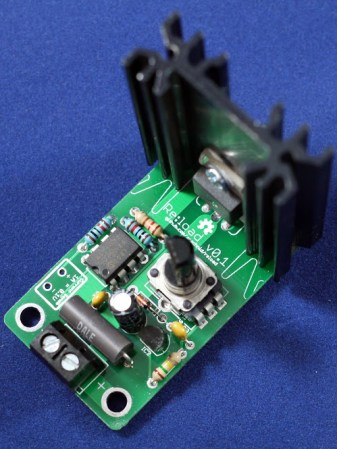
[Nick] was looking for a load to test out a power supply, and found commercial offerings to be too large, too powerful, and most importantly, too expensive. This lead to the design of the Re:load, his open source alternative.
Like other constant current sources, the Re:load uses an opamp to control a pass element. While most constant current loads will just use a transistor, [Nick] opted for a BTS117 smart low side switch IC. This device has a built in current limiter, over-voltage protection, over-temperature protection, and short circuit protection, which makes it much safer. The project write up goes into detail on how the device works.
If you need a constant current load, [Nick] is selling kits on Tindie. All the design files are available on Github so that you can build your own.


Thanks for the attention!
Note the link to Github goes to the old repository URL. It’s now at https://github.com/arachnidlabs/reload/
i dont see any reverse polarity protection in the circuit.
you can install a diode across the inputs and wire a fuse or breaker inline with the unit to protect against reverse polarity.
The opamp power supply is protected against reverse polarity by a small schottky diode. The main FET doesn’t require reverse polarity protection directly – its body diode will conduct in the reverse direction.
If you put enough power through it in reverse you could potentially damage the shunt resistor or the FET, but it would take a lot of current for a sustained period. This could be protected against with a diode in the main current path, but it’d have to be a rather chunky one to handle 6+ amps, unfortunately. I concluded that wasn’t practical, but I might revisit it as an option.
THANKS i have been needing one of these!
time to break out the breadbord!
Wow that Infinion BTS141 has some fantastic regulation at quite a range of Vin. I have been looking for a FET exactly like this for another project so thanks to the post!
Well, thank you a lot! I’ve been looking for a dummy load to test some power supply projects and this one fits my needs as a gloove!
Are the tabs of those BTS117 connected to any of the legs? The datasheet isn’t very helpful with this question…
Looks like the truncated pin 2 on the the TO-263 package implies the tab is tied to that pin, although not stated outright.
From the article:
“Most DIY adjustable loads use regular FETs or BJTs as the main pass elements, but this made me nervous. These devices don’t have any overtemperature protection built in, so they’ll happily self-destruct if you put too much power through them.”
Unfortunately, I don’t think the overtemperature/overcurrent protection will afford as much protection as the author thinks, because he’s using the device in an unintended way.
The BTS117 contains a power MOSFET intended for hard switching. Power MOSFETs are actually composed of many smaller MOSFETs cells in parallel, and they don’t have exactly the same characteristics. In particular, their turn-on voltages differ slightly. This isn’t an issue when you’re hard switching, but when operating the device in the linear region as is done here, some will be turned on more than others; leading to uneven current sharing, and possible overheating and damage to individual cells.
This cannot be detected with overtemperature/overcurrent sensing, nor protected against with heatsinks. The only sure method to insure long-term reliability is to derate maximum MOSFET current to a value typically 50% of the normal rating, since that rating is for the intended use of hard switching only.
Still, I like it, and would use it at the derated currents; relying on the overtemperature/overcurrent protection to protect only against the occasional “oops”.
That’s a good point about the parallel on-die fets. However the BTS117 data sheet does imply there is a single N channel vertical MOSFET and explicitly says, “analog driving possible”. Nowhere in the data sheets is protection de-rated for analog applications. But to be fair, this may just be ambiguity in the data sheet.
The datasheet does specifically call out “analog driving possible”. I designed it well within the safety limits, though: the BTS117 has a max current of 7A and a nominal load current of 3.5A, and the re:load is rated at 3A. The Epic Re:load uses the BTS141, which is rated at 25/12 and is driven at no more than 6A.
Pretty nice. When I needed to load test a power supply I made I just used a bunch of incandescent light bulbs. It was simple, and easy, and those things can really soak up some power.
I normally use a LM317 circuit. it took me about 10 minutes to make and cost ~$3, just some perfboard, a LM317 and a resistor.
The differences are several. For a start, you can’t adjust the current on that. The LM317 also has a reference voltage of 1.25 volts, meaning your resistor has to drop 1.25 volts across it, which requires very large resistors for high currents.