This demonstration fixes the power supply of a DVD player, but the skills transcend this one application. [Alan] walks us through the process of repairing a power supply (translated) on a simple consumer electronics unit.
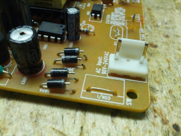
Obviously this starts by cracking open the dead device and verifying that the culprit is the power supply. [Alan] then removes that board from the chassis and gets down to work with a visual inspection. He’s got several images which illustrate things to look for; blistered electrolytic capacitors, cracked solder joins, scorch marks, etc. In his case there’s obviously a burnt out fuse, but that merely protects the hardware from further damage, it’s not the cause. Next he examines the diodes of the bridge rectifier. These need to be removed from the system to do so, which he accomplishes by clipping one end of each as seen above. He found that two diodes on one side of the bridge had broken down. After replacing them he tries a new fuse which immediately burns out. But a quick swap of the capacitors and he gets the thing back up and running.
We perk up every time we see this type of repair hack. We figure if we can build our own hobby electronics we should be able to fix the cheap devices like this one.


Can someone explain how to test those diodes? Is he using the meter in continuity mode? Also, black dots on caps = blown or leaky correct? I know this is pretty basic stuff, but I got lost in translation. Thanks!
A diode can be tested with a meter by placing the leads across it, noting the reading, then reversing the leads. It should read much higher in one direction than the other (this is the readers digest description!!). As for the cap in the picture, it looks like a pen mark. If they’re bulged up etc – that’s a visual sign of death.
Oops – place leads across it IN OHMS MODE
> Is he using the meter in continuity mode?
Yes, checking continuity in both sides only one side should work. Two sides working or none = bad diode.
>Also, black dots on caps = blown or leaky correct?
It probably had a bad smell as it “just smoked”.
I´m not an expert so I could be wrong.
Edit… I’m dumb… my multi has a diode function that I’ve never used… brain fart. Happy Friday!
yeah, diode mode, it should read ~0.7 if its good.
Depending on the diode type …
Only if it’s out of circuit with nothing connected to it. In circuit that will not work.
not dumb, but let me lend you some experience, testing diodes can be simple, but you have to check them both ways, make sure they haven’t shorted out. and on rare occasions it’s necessary to remove them for testing. On caps? It’s best to remove them if you want to check them for accuracy, but if the top scoring is ruptured, or there is ANY kind of bulge, it’s best to go ahead and replace them. I find electronics with mismatched voltage all the time, and when I replace those, I make sure to get all the same voltage and matched to the cap with the highest voltage rating.
Thanks for all the tips!
Wait a sec, I’ve seen mismatched voltage caps before, is it because they’re skirting the bottom line or a design consideration??
It’s a design consideration. Consumer electronics often have a few different supply rails at different voltages. The physical size and cost of the capacitor is usually directly related to its voltage, so capacitors only just high enough in voltage will often be chosen in order to reduce board footprint and cost. That’s why you might find, say, 6.3V and 16V and 35V and 400V capacitors in the same design – 6.3 for 3.3/5V rails, 16 for 12V rails, 35V for intermediate rails sometimes (24V or so), 400V for autoranging rectified AC input. To make all the caps 400V (or even 35V) at the same capacitance would increase the size of the device dramatically – as well as the cost of the components themselves.
Well when I see 3 different voltages for caps run in parallel, and the smallest voltage has blown, I don’t care if its a design consideration or not, I replace them with all the same voltage, usually the higher of the set. since the function of these caps are typically to even out the dc after the rectifier, and have a voltage regulator after the caps, the only way you can go wrong is with too small of a cap, but I usually keep it in the 25v to 35v range as a limit
Most DMMs have a diode mode. That’s the mode he used. And the Cap with the dot smoked out. Not exploded, but functionally, still dead.
Please remember when testing that even if the device is unplugged, Capacitors still hold a charge for a long time and can cause serious injury. Don’t be dumb.
Diodes are one way check valves for current. When they are bad they allow current in both directions. When good they permit the flow in one direction but stop it in the oposite direction.
Set your multi-meter to either a diode test, a continuity test, or an Ohms test. (all 3 tests are fundamentally the same)
You have to isolate at least one leg of the diode to prevent you from getting a false reading from the rest of the circuit.
Using the probes on either side of the diode should result in an open circuit in one direction and a closed circuit in the oposite. So touch the black probe to one side and the red to the other side. Record the finding. Then repeat with black on the other side of the diode and red where the black was. If it shows that it not connected (just like if the probes in the air). And connected (beeps, shows a nominal resistance, or gives a 0000) The diode is MOST likely fine.
In the circuit shown was using 4 desecrate diodes but there are some 4 in 1 diode bridges that exist and may require you to replace the full bridge. Luckily they are relatively inexpensive even from Radio Shack.
Hope this helps. Stay Safe.
Thanks for the safety tip and the how-to. I learned my lesson about capacitor safety at a very young age when I got shocked by one from a disposable camera =)
what’s a desecrate diode? Do you mean 4 discrete component diodes? Incorrect terminology can be devastatingly misleading, especially when you are trying to explain something new to someone!
A desecrate diode must be a type that will send you to hell when used.
A discrete diode is, of course, a single diode in a package, like the pictures show.
Is there a howto for the extremely expensive and very fragile apple powerbook power supplies?
I know that it’s usually flaky connector wiring, (or dirt on the magsafe connector) – but sometimes, it seems like it’s inside the white-box-transformer. (IMO – least value for the money consumer-product out there, today; magsafe is cool, but these power supplies don’t stand up to day-to-day use.)
I have repaired quite a few switching psus and i have some pointers to add to this.
100% of the time (in my experience, and after eliminating such obvious faults as broken cords and broken connectors) the fault will be one of these:
Bad capacitors on the secondary side (low voltage), 50% of the time
Bad capacitors on the primary side (high voltage), 5%
Broken rectifier or transistor on the primary side, 45%. This is however often caused by:
Broken switchmode controller (it’s usually very hard to find a new one without putting in way too much work)
I used to repair lots of switch mode supplies from arcade games. About 75% of the time the fault for a dead psu was a high value resistor (100k or more) in the primary side feeding the kick start circuit.
I have seen this same fault in many other supplies and is now usually the first thing I will check.
I knew it even before I started reading… Bad Chinese caps – planned obsolescence.
Indeed, any monitor/tv/cdplayer/etc that does not power on or only power up after repeated attempts chould be checked first for cheap/bad caps.
DO realise there are different types of capacitors, in the power supply part you typically want caps with a low ESR/ impedance , if you replace those with an other cheapo “standard” capacitor it might even not work (or not for long).
They cost a little bit more, but it’s worth to use low ESR/ impedance if you’re trying to resurrect power supplies.
I’m surprised more hardware hackers don’t repair their devices. It’s how I got started with electronics, repair CB radios, TVs, VCRs, and various small kitchen appliances. I’d really suggest anyone looking to expand their skillset to begin with kitchen appliances since they tend to be the simplest but have a wide range of techniques depending on vendor and function of the circuits found inside.
Kids these days – if it can’t be fixed by debugging the microcontroller code, then it’s off to the junk bin.
//kidding – but just barely//
http://badcaps.net/ is a good place to go for info.
what are the value/s of those 2 resistors beside the power IC of the DVD player.. i cant read it anymore coz it burns… pls reply … thanks and more power!!!
My DVD power supply is not switching on , but fuse is working. What would be the problem and to find it?
Yaaah t z a bit trick for u if u are not a Technician bt 1st u have to check your capacitors if they shorted u can see some acid on the top and look for signs of short on your circuit board to other components
Hey,my dvd’s plug blew off and it was non fused coz the DVD had an internal fuse already….i have tried to connect the dvd with a new but fused plug but it wont work …. is there a way to remove the fuse from a new plug and still keep the DVD working??
Hi, I have a CLD CSPS 16E SMPS 16 channel power supply
there is an IC in it, near to heat sink attached with transistor #W11NM80
there is no code on the IC, there is a chit pasted on it, its written X53 on it
How can i find the name of the IC, is there any way to find the name/code
Or if anyone can help me with the name/code of the IC.
thanks
Vinay Ramani
+91-9997433881
what is the name/code of the IC on U601
If all diodes resistors capacitors and transistors are good but still no power what do you do
I appreciate the help you offer through the site… Am still new in electronics…. Plz…, i need more guide… My fan power supply blew, guide me wot to do… Even my charger…
My LG dvd goes on and then off immediately. What can the problem be?
My dvd blew,but the capacitor is still intact.when i remove the power section,i discover that current enters the system but cannot pass to the transformer.please what shall i do?
Pls kindky tell me why my LG dvd is rejecting power when i plug it to the AC mains the power will just spark but the power is not working pls what. Coud be the problem
what can cause problem on china tvs 14 inch if you replace the fuse when you make the tv on it blows the fuse
On a LG type RH399H, on the power supply board, on the 16 pin connector to the outside world: Can you please give the voltages that should exist at pins ‘FD(-)’ and ‘FD(+)’ at one end of said connector? Thanks!
My dvd player is always open close load open . Its not work.why?
My ecco DVD player power supply always burn out diodes whenever I fixed them so am tired of buying new diodes what can be the problem, please help me out
smps ic numbar
I’ve had my portable DVD player a few months. The problem is the plug-in. In the DVD player it broke when I plugged it in. What to do to fix it .
My hundai dvd player wont power up after lightning and thunder
found in a new dvd smps that, it is working, but all dc outputs are lower than rated . can any body suggest for the rectification
Can somebody help me with my LG home theater DH3120 is totally dead with no sign of life , the fuse is good but when I test the secondary voltages , some are missing some are there now I need some schematics for the power supply.
Hi, anyone can advise on how to find out what IC chip used on board of the dvd player power supply panel due to the burned state caused disfigured to identify the part number. I am referring to the martin ranger HD DVD 800 model.