http://www.youtube.com/watch?v=D9WPZjcEOdI
The RedBull Creation contest begins today.
Last year, we had a ton of fun competing in the RedBull creation contest. The idea is that RedBull hosts this big contest where teams compete by making awesome stuff. Finalists get to take a trip to Brooklyn for a build off extravaganza. Frankly, we think this is how ALL advertising budgets should be spent.
This year, however, we will not be participating as a team in the contest. We’ll be helping judge it!
The hardware:
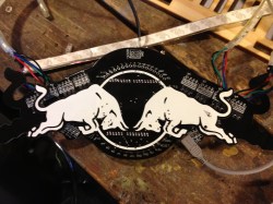
In previous years, RedBull has sent out some custom hardware for people to use. Last year it was basically an Arduino on a custom PCB with some cool touch sensors. This year, they’ve sent out this multi purpose LED controller shield that looks pretty impressive.
You can see all the details along with a breakdown of the board from the creator himself, after the break.
From [JoeJoe], the creator of the board:
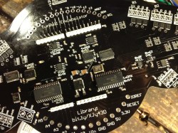
Basically, it is kind of an LED lighting multi-tool with some extra sensors and output devices on-board. The board is controlled over I2C using an Arduino Uno R3, or you can air-wire pretty much any device that supports 400KHz (fast mode) I2C to the breakout pads. We’ve tested it with some of custom networked devices and with Raspberry Pi, for example. The I2C addresses of each device are written on the silkscreen of the board, though some peripherals (on PIC microcontrollers for example) expect you to use that address shifted one bit to the left (they don’t automatically add in the low read/write bit).Onboard you will find the following:
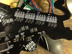
- Two smart devices for driving 12V RGB LED strip. Each device will drive up to four strips, for a total of 24 discrete channels. There are built-in macros for color fades over time, pulsing, random color sweeps, etc which offload the necessity of controlling of these effects from the Arduino. To use these, follow the wiring specified on the silkscreen for the strip, and hook up at 12V power supply to the pads/terminal block at the top of the board. I *suppose* these could also be used to PWM any sort of device that was within the current/power specs of the MOSFET, but I’d definitely suggest snubber diodes if you were to attempt any DC motor controlling. We included 5M of RGB strip in the package.
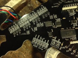
- One “addressable LED strip multi-tool” device. This handles the timing for controlling up to 256 RGB pixels of addressable strip based on the WS2811, WS2801, or LPD8806 IC. We have included 1M of high-density WS2811 strip, which is the default mode for the device. Using the library macros, you can write a framebuffer to the strip, set up gradients between two colors across a number of pixels, rotate or auto-rotate the current framebuffer at a given speed, and create a effects such as ‘comet’ chase. To use this device, you’ll hook 5v up to the marked location in the lower left of the board.
- One DMX driving device. This is in the lower right of the board, and is for driving 3-channel (RGB mode) DMX fixtures. You can cut apart a 3-pin XLR cable and connect this to LED PAR cans, or any other sort of DMX fixture (fog machine maybe?). Using the library you can write a universe of DMX which will be output continuously to the A and B pins with correct timing.
- One 512Kbit EEPROM, which may be preloaded with something interesting. We included very rudimentary read/write functions for dealing with this on the byte level, but there are better 24LC512 libraries out there that could be used also.
- One tri-axis MEMS accelerometer. The library has functions to read X,Y, and Z. This Kionix unit also has a lot of functionality that we haven’t implemented such as high-pass filtering, tap and double detection, orientation change detection, and adjustable sensitivity (+2g,+4g,+6g).
- One 12-bit DAC. This will output a waveform between 0 and 3.3V which I’m sure someone will find a good use for.
- One temperature sensor. The library has basic functions to read the current temperature and convert the result to Celsius.
- One generally awesome looking circuit board which will nest lovingly with last year’s bullduino in eternal harmony.
For those that haven’t seen the video this campaign was inspired by:


Bonus Points to Red Bull for the video.
I’ll just leave this here: http://www.youtube.com/watch?v=rLDgQg6bq7o
Glad I’m not the only one who caught that. That video was shown in my freshman engineering class……
thanks, I totally forgot to include that video. It is there now.
Heh. Dingle arm. Didn’t somebody get fired for a dongle comment at pycon?
Y U NO PARTICIPATE??/!!one
also still waiting for live streams…
ohh! I allmost forgot – it’s red bull contest, but there’s something wrong in the right corner of your video (1:28 – 2:03)…
Ha, yeah. Well, that was an accident, but hey, I don’t work for RedBull, so no big deal I guess.
I’m judging this year!
Caleb that’s abit saddening but all the same hehe it was fun last year am sure other makers can make it just as fun.
I hope they atleast spawn creative ideas like the ones you guys had last year to keep us transfixed and perfectly entertained. Building is fun but not if you have to sit through even 24 hours of someone else doing it.
:( too bad they won’t send a kit to Canada.
Agreed. Apparently we’re not good enough for these competitions. What a shame.
Yeah, I mainly wanted the free hardware though lol.
Maybe I’ll submit a simulation of what caffeine abuse does to the Cardiovascular system over time.
Give it another 10 years. Then start buying stock in companies that make heart-attack recuperation drugs.
mes is gots to gets mes one of them Turbo Encabulator thingamjigs.
WARNING : video is a caused a real LOL response.
… is that you, Jar Jar Binks?
But is the PCB made of prefabulated amulite?
They didn’t include the lunar wane shafts. Terrible.
Promoting Red Bull with a can of Monster in the shot! Tut tut! lol
only us. this sucks
Please get a real microphone for your videos, your video starts out with strong sound when you’re facing the camera, then goes directly to mumble mumble mumble, then goes back to audible sound at the end.
A cheapie little bluetooth clip on mic should solve the problem.
Anybody care to read their term of service?
Pretty gruesome stuff…
I just got my kit from redbull. I am going to be tinkering tonight!
WE finally got our red bull creation video posted. check out the gorilla dance party on wheels: https://www.youtube.com/watch?v=RFgh1NvOJmc