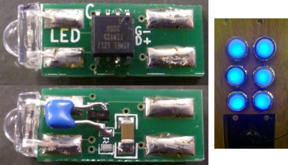
These arcade buttons started out as illuminated buttons. But they were bulb-based which only allowed for one color. [Jon] and his friends at the Leeds Hackspace wanted to find a way to retro fit them with RGB LEDs, without changing the buttons themselves. The hack lets them replace the bulb with an addressable circuit board. The really interesting thing about it is that there is no separate interface for addressing. The communications happen on the voltage bus itself.
After deciding to include a microcontroller inside the button they built a test version using some protoboard to see if it would fit. Indeed there was enough room and the proof-of-concept led to the factory spun board which you see above. It has pads for two of the four LED module feet on either side, with the opposite end of the board fitting into the bulb receptacle. The voltage line is pulsed to send commands to the microcontroller. We’re interested in finding out exactly how that works but we’ll have to dig through the code before unlocking the secret.


These are sick! How do I build the PCB? Also do you guys sell these as full kits?
i dont want to be ‘that guy’ but did they really need a micro for each light?
I think by virtue of the control signals they did.
You mean in the photo above? I think that’s how the modules come from the manufacturer. And to make a serial-interfaced, addressable, RGB LED? Can you think of a better way? I suppose one MCU could control several lights, but selling them singly is the way they think they’ll sell best. How much do the Atmel Tinys cost in medium quantities? I’d imagine they make a fair profit on a reasonable price.
The RGB ribbon LEDs are similar, and very popular. That’s just how cheap MCUs are. It’s revolutionary! And it’s made so much clever stuff so much easier and indeed possible. Crap from the dollar store contains more computing power than went to the Moon.
I know how you feel, worrying about wasted MIPS, but that’s how good chip tech is now. It’s as cheap to turn out MCUs as it is NAND gates and 555s. Isn’t that wonderful?
“I think that’s how the modules come from the manufacturer”
These were fully custom designed/made.
They use a pulse-width protocol sent on the positive power rail with three symbols: a short low pulse for a 0 bit, a slightly longer low pulse for 1 and an even longer low pulse for a break symbol. The communications line, because it’s also the power rail, idles at a logic high level. In this sense it’s like most other 1-wire protocols. This, however, is much more timing-sensitive than most, as the AVR is clocked by its internal 8MHz oscillator and they’re using spinwaits for timing, where a 0 bit is less than 4 iterations, a 1 bit is between 4 and 8 and a break symbol is greater than 8 iterations. At 8MHz these correspond to about 4us respectively.
Oops, the comment form mangled my formatting. A 0 bit is less than 2us, a 1 is less than 4us and a break is longer than 4us.
I often thought a good way of sending 2-way data and power over 2 pins would be for a transmitter to vary the supply voltage for 0 and 1, with the receiver varying it’s current consumption (ie effective resistance). This way I suppose needs some capacitance on-chip, and low-power operation, but is simple to interface to.
Old-school “current loop” communication works this way, more or less, as does analog wired phone service – both deliver power and data quite long distances over one pair of wires. Other modern low-pin-count power-carrying interfaces (USB, Thunderbolt, FireWire, Lightning, PoE) separate data and power because the electrical demands of high-speed data and power are just so different.
To me, Power Over Ethernet looked like it faced problems from several angles. 48v is a standard telecom voltage, maybe that’s why the range is around that area. Using the thousands of miles of conductors previously marked “unused” turned out handy. I dunno why 8-core was specified originally, when only 4 were ever used in the standard. Or why people actually obeyed it, but there y’go, worked out well.
At least separate wires mean there’s no need to modulate data on the voltage, which would complicated things quite a lot at the sort of data rate Ethernet works at nowadays.
48v is quite high. I know the idea is the receiving device uses DC-DC convertors to change it to 3.3v, or 2.5 or 1.8 or whatever, and higher voltage means more watts over thin cable. I think 60v is the threshold of “ouch” for bare skin.
I suppose it has it’s uses in powering Wifi and microwave transmitters at the tops of towers and things. Ethernet’s not like USB in that there’s not much hot-plugging, most plugs stay plugged for years.
Still the whole thing looks a bit kludgey. It’s whatever the opposite of a miracle is, these days, that high quality PSUs in every PC can output dozens of well-regulated amps, but getting it out to charge a phone requires abusing the USB standard, plugging 2 plugs in parallel, or special black “high current” charging plugs.
It’s just annoying to see things starved of power when they’re right next to a mains socket. There really should be a standard low-voltage connector by now. The DC barrel plug would do. Maybe use smaller plugs for higher voltages, to avoid damage from people plugging the wrong one in. Or a simple resistor that lets the socket know the required voltage. Stuff doesn’t come with as many PSUs nowadays, modems and scanners and some small hard drives scrape by with 2.5W. But there’s room for so much more, and I wonder why nobody’s done it. It’d take 5 minutes to decide on which existing plug to use, then get a couple of the Chinese giants to include it, IEEE standards or not.
True Power-over-Ethernet can use all 4 pairs, e.g. in Gigabit (1000baseT) and the power is not carried over spare pairs, it’s provided as common-mode phantom power, owing to the fact that Ethernet links are coupled galvanically (through transformers at either end.) This means power and data pulses absolutely do travel on the same wires. There’s also a power-class auto-negotiation protocol where an IC in the end equipment (VoIP phone, wireless AP) puts a characteristic resistance across the power link to tell the switch (or injector) how much energy it will need. These complexities plus others are the reason a lot of people monkey-rig power over spare pairs and call it PoE (when it is clearly not.)
I hate to be “that guy” as well… but I guess these people had never visited ultimarc, groovygamegear or any of the other vendors that offer products specifically for controlling leds lights for illuminated arcade controls. You can get an avr setup specifically to do this for around 30-40 dollars, and ready made rgb led modules that snap right on to the bottom of the pushbuttons. More importantly, their products are compatible with the various emulator-related software out there that control your leds.
but they’re all expensive. Not sure I’d want to go for the design in the OP but the prices at the places you’ve mentioned are all more than likely exactly why they built their own.
addressable leds are insanely cheap, even if you just buy a strip, with the right buttons (sanwa/siemitsu clear edge) you can get some illumination.
just to give you an idea:
http://www.youtube.com/watch?v=YxvfL1qmVDQ
Really? their protocol is nearly identical to the 1wire protocol that has been around for decades. Me thinks that HAD editors need to do more hacking and play with the wonderful world of 1wire…
Yep, first send the + voltage, and connect the wire to a capacitor to store the volts. Then send the – and switch the wire to the other end. 1-wire power supply, easy!